 Review Article
An Expert System for Designing Mold Tooling for Sand Casting
Mohammed Ahmed Elbashier1 and Osama Mohammed Elmardi Suleiman Khayal2 *
1Deptartment of Manufacturing Engineering, Nile Valley University, Atbara, Sudan
2Deptment of Mechanical Engineering, Nile Valley University, Atbara, Sudan
Osama Mohammed Elmardi Suleiman Khayal, Deptment of Mechanical Engineering, Nile Valley University, Atbara, Sudan.
Received Date: September 14, 2019; Published Date: October 11, 2019
Abstract
The three major steps in developing a new casting product include product design, tooling development and foundry experimentation trials. The sand mold tooling development comprises determining the parting line; designing and making the patterns, cores, and cores prints, which with proving accounts take nearly 70% of the new casting developing lead-time [1].
This study concerns the creation of an expert system for selection of parting line, design of patterns, cores, and cores prints using AutoCAD 2004 programming language [2-13].
Keywords: Expert system; Mold tooling; Auto CAD; Template file; Customization; Parting line; Pattern; Core; Core print
Introduction
Sand casting is the most versatile among the manufacturing methods and gives the Engineers the freedom to design complex parts from unlimited number of metals and alloys.
Sand casting is a manufacturing process where the molten metal is poured into the expendable sand mold cavity either by gravity or by force, where it solidifies to form the cavity shape. 3D object formed by this process is also called casting. Most common sand castings include Engine blocks, cylinder heads etc.
Characteristics of sand casting
Over 70% of all metal castings are produced via a sand casting process. Sand casting can be produced in a wide range of sizes from small statues to parts weighs over 100 tons. Very complex parts can be produced easily and in one piece, but with low dimensional accuracy, poor surface finish, and high adaptability which could be used for handling mass production.
Steps of sand casting process
The following are the seven main steps in sand casting cycle:
Pattern making step: in which a replica of the object to be cast should be made of suitable material. The pattern is normally oversized to allow for metal shrinkage during cooling phase.
Mold making step: In this step a sand mold is formed by packing sand into the mold around the pattern. Sand mold is divided into two halves, top half is called the “Cope” and bottom part is called the “Drag”. When the pattern is removed the cavity it forms remains for pouring the molten metal. Mold will have other features such as sprue, runners, gate, pouring cup, riser etc. which is discussed in detail later.
Clamping step: It involves the two mold halves cope and drag must be securely clamped together so as to be ready for pouring metal.
Pouring: Molten metal is maintained at a set temperature. Molten metal is poured in as quickly as possible so as to avoid early solidification.
Solidification: Poured molten metal will begin to cool and solidify once its inside the cavity. Most of the possible sand-casting defects are introduced at this solidification stage.
Extraction: Once the cooling period elapses the mold can be shaken out/broken off.
Trimming: It involves cleaning and removing the section that connected to the main part such as runner, sprue etc.
Advantages of sand casting
• Large parts can be produced.
• Complicated shapes could be casted easily.
• A wide spectrum of choices to select from.
• Tooling and equipment cost is low compared to some other metal forming processes.
• Scrap metal could be recycled.
• Short lead compared to other similar processes.
The three major stages in developing a new casting include product design, tooling development and foundry trials [1]. A casting design would be useless unless the design can be made in the foundry, satisfying all the functional requirements within budget. The cost effectiveness of the process depends highly on the design as this is reflected on the final cast. The decisions made during the design changes would make a big impact on the cost and some of the disadvantages of sand casting can be avoided by designing the part to suit casting. However, there are key sand casting design guidelines to be followed in order to keep costs down. Engineering product designers should understand the reasons as to why some of these techniques are used and consider those during the design stages of the cast.
The tooling development is a critical activity linking product design and manufacturing. The tooling comprises patterns and core boxes (i.e. for sand casting) or dies (i.e. for die casting and investment casting). Tooling design can be further classified as design of main cavity (or the pattern for producing the cavity), other cavities and accessories. The main cavity is produced by bringing together two or more segments of molds, involves selection of the best orientation of part in the mold and determining the parting line. The mold may have a single or multiple cavity depending on part size, requirement and other considerations. Internal cavities in the part, such as holes and undercuts (portions which hinder removal of pattern from mold or part from die), are produced by cores. This requires identification of cored features, design of cores (including their supports, called prints in sand casting) and core boxes for producing the cores. Proper allowances have to be incorporated in the mold cavity and cores for part shrinkage, distortion and subsequent machining. Draft or taper has to be given to facilitate easy removal of the pattern from sand mold or casting from permanent mold. Other cavities include feeders or risers (number, location, shape and, dimensions) to compensate for volumetric shrinkage and gating channels (sprue, runner and in gates) to lead molten metal into the mold. Accessories include cooling, guiding and ejection systems, especially for dies.
The average lead-time for launching a new casting in a foundry may be several weeks or months (depending on the casting complexity), of which tooling development and proving accounts for nearly 70%. The lead-time can be reduced by more than half, especially for intricate castings, using computer-aided systems for product design, tooling development and process optimization [1]. The aim of this paper is to propose an expert system for tooling development using a solid modelling program (AutoCAD 2004) to aid the foundry personnel to reduce the lead time of launching a new casting.
The Software Analysis and Design
The expert system is designed to hold all the knowledge base built from practice expertise and the well-developed casting technology. The system is developed to select and analyse the parting line, design the patterns, design and analyse cores and cores prints. The work in the system starts by drawing the solid model of the cast product and results on complete dimension mold tools ready for manufacturing
The expert system interacts with user through AutoCAD normal window (model space and layout space). The work in AutoCAD divided into two parts:
First: creating a Drawing Template File contains standard settings, which help in drawing, modifying, and presenting the solid model of the casted component. The user can either work on them or modify them.
Second: using AutoCAD 2004 customization capability to collect group of tools and commands that help in determining the parting line, modifying the solid model of the casted component to obtain the parts of pattern and core, and providing the design and analyse data in a form of four drop down list menus, and corresponding toolbars.
The settings of the template file are to:
• select a metric measurement system and determination of precision;
• determine of the drawing limits with 1:2 drawing scale;
• create text and dimension styles;
• load different line types one of them (parting line) is created outside AutoCAD using text editor;
• create collection of layers and layer filters;
• Create eight layout sheets named with orthogonal projections of mold segments.
The first group of tools and command named Parting line helps the designer in orienting and parting the solid model and drawing the parting line. The second group of tools and command named Pattern helps in adding the allowances and colors to the part surfaces to obtain the pattern. The third group of tools and command named Core helps in extruding the cores and core prints from holes.
The fourth group of tools and command named Data and Analysis helps in accessing the tables and slides which contains the design data, and also helps in inserting and extracting the analysis data, inserting title block data, and contains the inquiry tools.
In addition to that AutoCAD is linked with three Microsoft Access files contain database tables help in design, creating group of six slides contains recommended data presented automatically through script file, and creating three Attributes Definitions files two for analysis data (core analysis and parting analysis) and the other for title block data.
The Support Files
The study includes six slide files and scripts command file.
• Three Microsoft access files for database table.
• Two AutoCAD attribute files for data analysis (core and parting analysis).
• Texts file for created parting line.
• Texts file for menus and toolbars.
Test Case Example
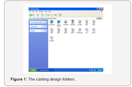
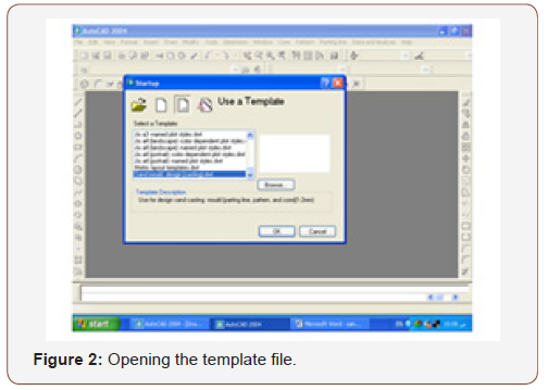
Step (1): Open the (sand mould design) template file from Start-up dialog box by using a Template button as shown in Figure 1 and Figure 2.
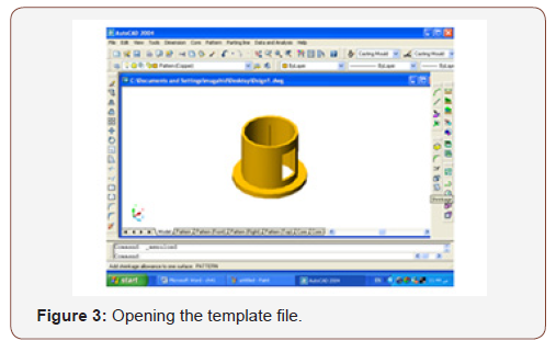
Step (2): Draw the solid model use AutoCAD solid modeling capability (Use special pattern’s layer in drawing the model) as shown in Figure 3.
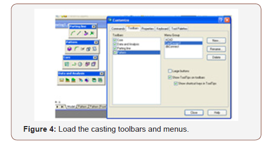
Step (3): Load the casting toolbars and menus to modify the model and create the parting line, pattern, core, and core print as shown in Figure 4.
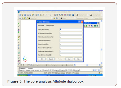
Step (4): Analyze the core and core print design as explained in Figure 5.
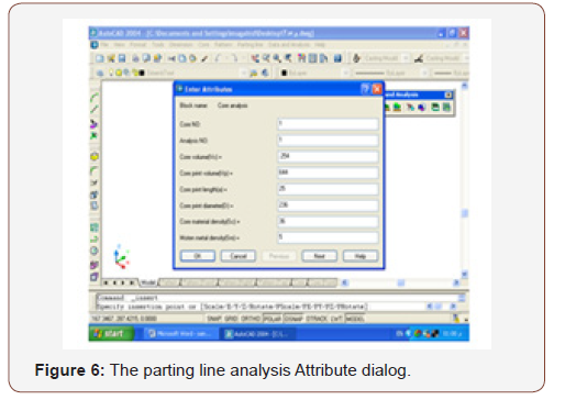
Step (5): Analyse the parting line alternatives as indicated in Figure 6.
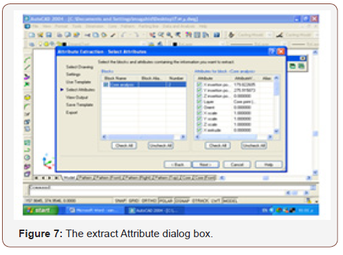
Step (6): Extract the analysis data to Microsoft Excel or text format as shown in Figure 7.
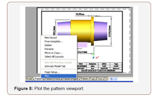
Step (7): Editing and printing the design as indicated in Figure 8.
Conclusion
The system was tested by designing known casting components in Sudan Railways Foundry, and alternative designs were suggested. After performing the analysis, the results aver the effectiveness of the system, the parts of pattern and core presented with dimensions and colors ready for manufacturing (the system succeeded). To obtain better results of this expert system the components of the system are preferred to be performed by an expert casting engineer, with good knowledge on using AutoCAD.
Acknowledgement
None.
Conflict of Interest
No conflict of interest.
References
- B Ravi (2005) Metal Casting: COMPUTER-AIDED DESIGN AND ANALYSIS (Book), First Edition, Prentice-Hall of India, New Delhi.
- George Omura (2003) Mastering AUTOCAD 2004 (Book), First Indian Edition, Manish Jain for BPB Publications.
- Heine RW (1967) Principals of Metal Casting (Book), McGraw-Hill.
- Sylvia JG (1972) Cast Metals Technology (Book), addition- Wesley.
- Rao PN (1998) Manufacturing Technology, Foundry, Forming and Welding (Book), Second Edition, Tata McGraw.
- Jain PL (1987) Principle of Foundry Technology, Third Edition, Tata McGraw.
- Steve Hurst (1996) Metal Casting, Appropriate technology in the small Foundry (Book), Intermediate Technology.
- MM Bandyopadhyay (1980) Irion and Steel Casting handbook, Small Business.
- Jain RK (2003) Production technology (Book), Sixteenth Edition, Khanna Publishers.
- Adil Elbashir (2003) An Expert System for Designing Gates & Risers, M.S. Thesis, Nile Valley University, Atbara-Sudan.
- B Ravi (2005) Computer-Aided Casting Design- Past, Present, and Future.
- M Nainy Nejad RC, Creese, B Ravi (1999) Research Issues in Computer-Aided Parting Design for Casting, AFS Transactions.
- J Norberto Pires, T Godinho, P Ferreira (2004) CAD interface for automatic robot welding programming”, Industrial Robot: International Journal, Emerald Group Publishing Limited, Pp. 31(1).
-
Osama Mohammed Elmardi Suleiman Khayal, Mohammed Ahmed Elbashier. An Expert System for Designing Mold Tooling for Sand Casting. Glob J Eng Sci. 3(4): 2019. GJES.MS.ID.000567.
-
Expert system, Mold tooling, Auto CAD, Template file, Customization, Parting line, Pattern, Core, Core print
-

This work is licensed under a Creative Commons Attribution-NonCommercial 4.0 International License.


