 Research Article
Air Conditioning Booster
Ehab Nader Tuffaha, Mechanical engineering, Hashemite University, Jordan.
Received Date: April 22, 2020; Published Date: May 22, 2020
Abstract
The study trying to utilize and allows to harness the natural and free solar energy gotten from the sun by converting the additional free enthalpy gotten as thermal and kinetic energy likewise into useful power; on other words the main concern is increasing the COP.
This type of AC will use as much solar energy as is available and convert the solar energy directly to replace the equivalent amount of AC power from the mains provider. Under optimum conditions, this can save up to 25% – 45 % of your mains power usage during the summer.
This will be most recent innovation in standalone power saving which is partially free of charge by the Sun.
The study aims to renovate the traditional refrigeration system which is normally known as compression refrigeration cycle everywhere in our buildings, so that it can be developed to take advantage of the free solar energy without complicated changes neither a completely demolishing.
Keywords: HVAC; Solar radiation; R 134a; Thermodynamics; Momentum
Introduction
Jordan is among of the most enthusiastic developing country to promote utilization of renewable energy, as very well known the solar radiation in Jordan average within 4500 Wh/m2 to8000 Wh/ m2.
More than 300 sunny days in Jordan driving us to think more seriously in renewable energy resources and somehow reduce dependence on oil consumption.
Basic thermodynamics statement that as a greater temperature difference between substances the faster heat flow, so once the refrigerant gas temperature increased then a heat rejection is higher; same what happened when the ambient temperature increases, less heat can be rejected from the air-cooled condenser to the hotter ambient.
The study here is utilizing thermal energy by using solar collectors see Figure 1.
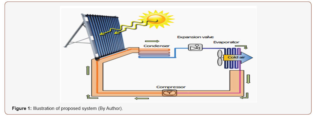
Adding an extra heat to the cycle in order to increase ΔT between condenser and surrounding environment. Not quite, but the future will be for renewable energy, however the first step should be renovating the transition phase of the hybridized types by paving the way for the renewable sources, as there is no doubt that renewable energy does not match in any way the traditional energy that we are accustomed to in term of cost neither the required efficiency.
Literature Review
The main point is to drive the point number 2’ of the below figure (P-H diagram) to point number 2, in other words add a kinetic energy to the system in order to increase the enthalpy (Figure 2).
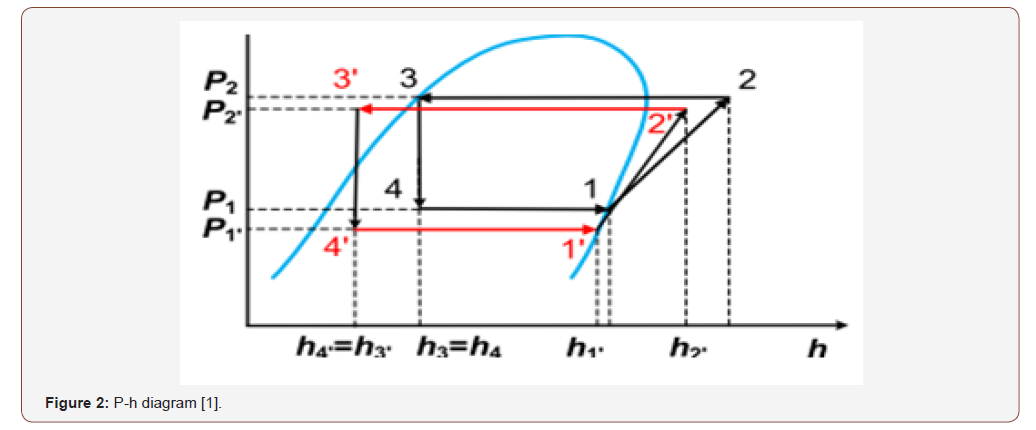
A heat exchanger will be used in this study to reach for a hybrid air conditioning system and achieve to targeted energy savings. By utilizing The First Law of Thermodynamics which is states that heat is a form of energy [1-5].
The First Law of Thermodynamics states that energy cannot be created or destroyed; so the sun radiation here or the heat itself will be the exerted energy to the closed refrigeration cycle.
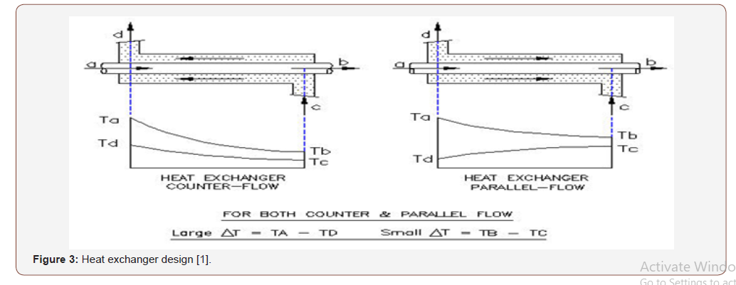
The desired thermal output and rate of heat transfer help determine the optimal type and design of heat exchanger as some heat exchanger designs offer greater heater transfer rates and can handle higher temperatures than other designs.
Methodology
Heat transferee calculations:
a) Qh = mh x Cph (Thou t-Thin) Versus b) Qc = mc x Cpc (Tc out-T c in)
Equation a here represent water system versus equation b for refrigeration cycle.
Where Q = heat energy (Joules, J) m = mass of a substance (kg) c = specific heat (unit’s J/kg∙K) Δt is a symbol meaning “the change in” temperatures
Tcout = Outlet refrigeration temperature from heat exchanger.
Tcin = Inlet refrigeration temperature from heat exchanger.
Thin = Water Inlet temperature from the solar collector to heat exchanger.

Note 1, For water
Assuming water inlet 85 c and outlet is 81c:
Q=500 GPM Delta T (F)
15 KW /3.5 =4 x 12000 =51429 BTU h
51429/ (500 x (185-177) = 10 GPM Which is 0.7 Kg/s let say = 1 Kg/s to be more reasonable.
Note 2 , For R 134 a
As discharge temperature almost 40 C so enthalpy is h2= 289kj/ kg , the same for suction line assume the temperature -10 C so enthalpy is h1= 245 kj/kg (Figure 3).
Now the refrigerant effect is h2 @ T =-40 C –h1 @ T -10 C =h2– h1= 244.5-289 =-44.5 kj/kg So for 1 KW we need 1 (Kj/s)/44.5 (Kj/ Kg) = 0.02 Kg/s ; so for 2 refrigeration Ton = 7 Kw we need :
7 x 0.02=0.2kg/s
Heat Exchanger Design


Efficiency of the System

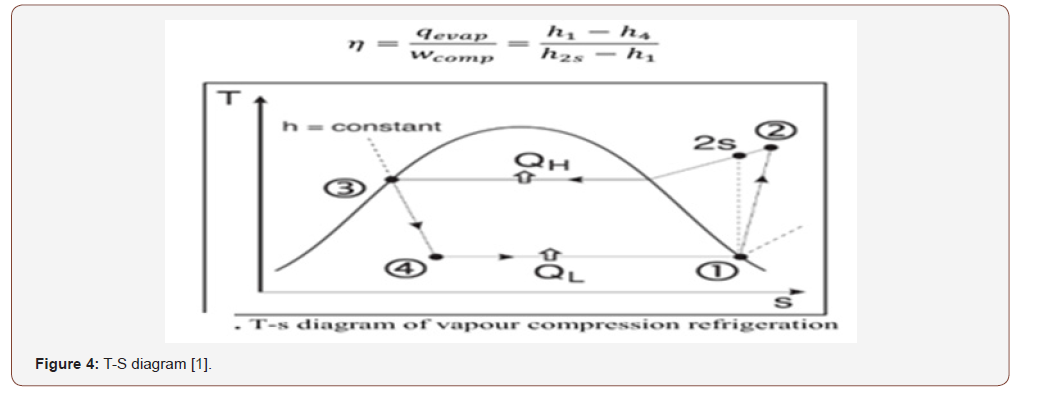
New COP = 249/46 =5.5 which is mean we increase our COP by 25 % from free solar radiation.
However, COP actually is increased more assuming constant pressure during thermal increasing whilst as below I will proof that new pressure has been increased and all values of the above should be taken @ 12 bar instead of 10 bar which is mean COP will be increased up to 35 % more.
System Design
The system will be as the below Figure 5:
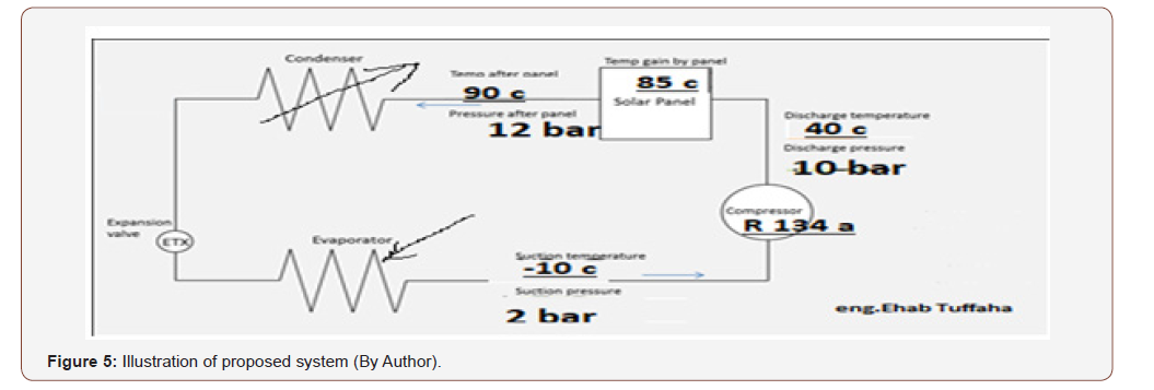
Evacuated heat pipes will be the source of heating, as calculated previously:
Now as previously we got from below equation:
Q=500 GPM ΔT (F)
15 KW /3.5 =4 x 12000 =51429 BTU h 51429/ (500 x (185- 177) = 10 GPM
Which is 0.7 Kg/s let say = 1 Kg/s to be more reasonable.
It seems we need 1 liter in one second so in one minute 60 liters, for factor of safety the tank will be 100 Liter. Or:
Pt = (4.2 × L × T) ÷ 3600. Pt is the power used to heat the water, in kWh, L is the number of litters of water that is being heated and T is the difference in temperature from what you started with, listed in degrees Celsius.
We need 4.18 KWh= 15048 Kj = m x 4.18 x (82-20) = 55 liter; let say 100 liters.
To get evacuated pipe size
The capacity of each pipe of 58 mm by 1.8 m length almost a 10 liter so we need a 10 heat pipes. Usually each house of 4 persons are requiring from 200 to 300-liter pipe collector so a 100 liter for such process could be connected easily without any new required collectors if we consider the diversity as well to guarantee the water outlet requirements and avoid the critical temperature of R134a which is 252 degree Fahrenheit or 122 degrees Celsius.
Mpemba Effect on the Refrigeration Cycle
The basic advantage is a quicker phase change from gas to liquid leading to a better sub cooling and that to less flash gas then more cooling capacity at the evaporator and with the control of the unit then to the original cooling capacity at the evaporator but with less compressor work. All the known formulas in thermodynamics can’t explain, because there is really none for the phase change except the amount of heat transferred at phase change.
We gain here 15 KW using our selected heat exchanger); Now a gas coming from a higher temperature has a much higher kinetic energy of the molecules and they kick much more into them as a result they can develop much quicker the interconnecting Vander Waals forces and as a result they liquefy quicker. Since the gas gets quicker liquid, the remaining way in the condenser is used to cool down the fully liquid further.
In order to get new pressure @ 90 C =363 k of refrigerant; we have to use Vander Waals force consider the below:

Where a & b are dimensions to be experimentally found. p = pressure, n= number of moles, T = temperature, V = volume and R = universal gas constant. Hence Its value will be nearby to general gas equation the given gas is at low pressure and high temperature.
PV = nRT; V = As x L, as the selected exchanger is 0.311m height,
P @ 90 C = 10 bar = 9.9 atm; V= 0.5 m3
R = 0.082 lt. atm /deg.k.mole
10 x 0.5= n x 0.082x 363
So n= 0.2
However as very known from
P1V = n1RT …; P2V = n2RT … Considering the volume is constant (Isochoric) as the heat exchanger is a small closed tank so: P2 X 0.5= 0.2 x 0.082 x 363 k ; So P2 =12 bar
Discussions and Ideas
Based on the below equations and numbers, a rapidly increasing in momentum during of heating the refrigerant gas R 134a:
As an estimation each pressure drop in heat exchanger 4m/ 100m and we have a 10 meters pipes so we have a 0.4 bar =4079 kgf/m2 (kg per sq. meter); let us multiply the factors as below:
0.2 kg/s (refrigerant flow rate) x 4079 kg/m2 x 0.02 m3/kg (specific volume @ 40 c & 2 bar) = 16 kg.m/s
This unit is a momentum, so let us try to get the momentum @ 90 c & 10 bar:
0.2 kg/s (refrigerant flow rate) x 4079 kg/m2 x 0.3m3/kg (specific volume @ 90 c & 10 bar) = 245 kg.m/s.
This is mean each change in momentum is a new specific impulse on other words this is producing a thrust force which is also a gain for the cycle.
Conclusion
• The system clearly shows that COP is increased from 4.3 to 5.5, by converting solar thermal energy to sub cooling additional for the refrigeration cycle.
• The system adds more 2 bars to the refrigeration cycle consequently increasing in the entropy as mean a quicker phase change due to quicker set-up of intermolecular bindings because of v Van der Waals forces yielding additional sub-cooling.
• The most important is we don’t have to increase condenser surface. It is very well capable to remove the additional heat, the Formula Q = alpha X surface x delta T. Alpha is heat transfer coefficient and does not change, If Delta T increases due to higher temperature of the refrigerant entering the condenser, the condenser just transfers more heat. The environment as the heat absorbing media is capable of taking up that additional heat. For more explanation, let say what happened with radiators: if you flush water with a temperature of 45 °C through the radiator, it does not provide that much heat as if you flush water through with a temperature of 90 °C so the radiator is capable of doing the job.
Basically W (KJ/Kg) = ∫p*dv, however the dv in heat exchanger considered zero by other words it’s an Isochoric Work When V is held constant and P changes W = 0 Because gas is not doing any work but as surrounding adds energy to internal energy of gas That’s why Cp is always greater than Cv Specific heat capacity at constant pressure is always greater than Specific heat capacity at constant volume, now once the gas goes through the condenser a quicker phase change occurred there cause When gas expands it has to do work to push environment to create space for its expansion by spending energy from its internal energy that’s why suddenly Gas cools down.
Suggestions
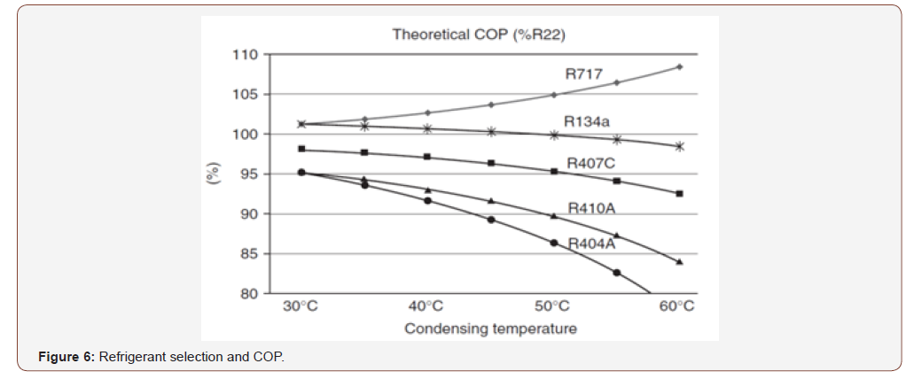
The below figure shows as condensing temperature increased the efficiency of system will be reduced for all refrigerant gasses except R 717 which is rapidly increased, am suggesting to apply this methodology for such refrigeration cycles with R 717 (Figure 6).
Addendum
Data Analysis
The below study shows if reduce refrigerant up to certain limit could be useful for COP, however should we not reach to the maximum temperature of 120 c which is the critical temperature, however power consumption is reduced accordingly (Table 1).
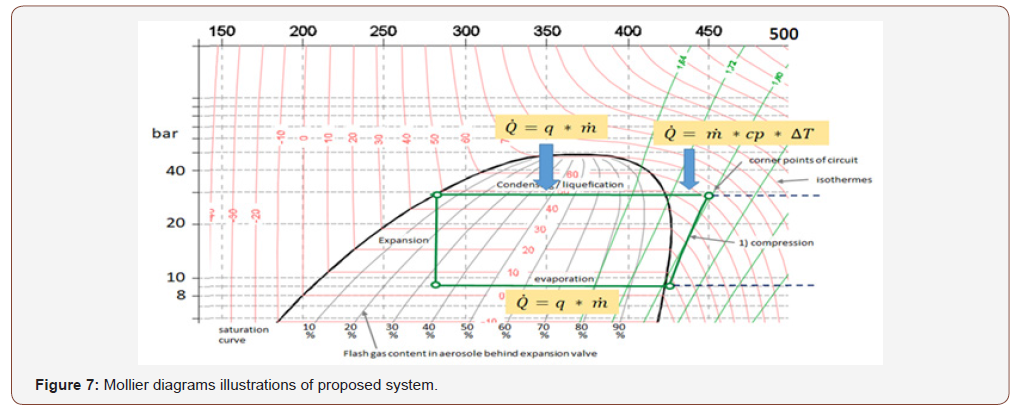
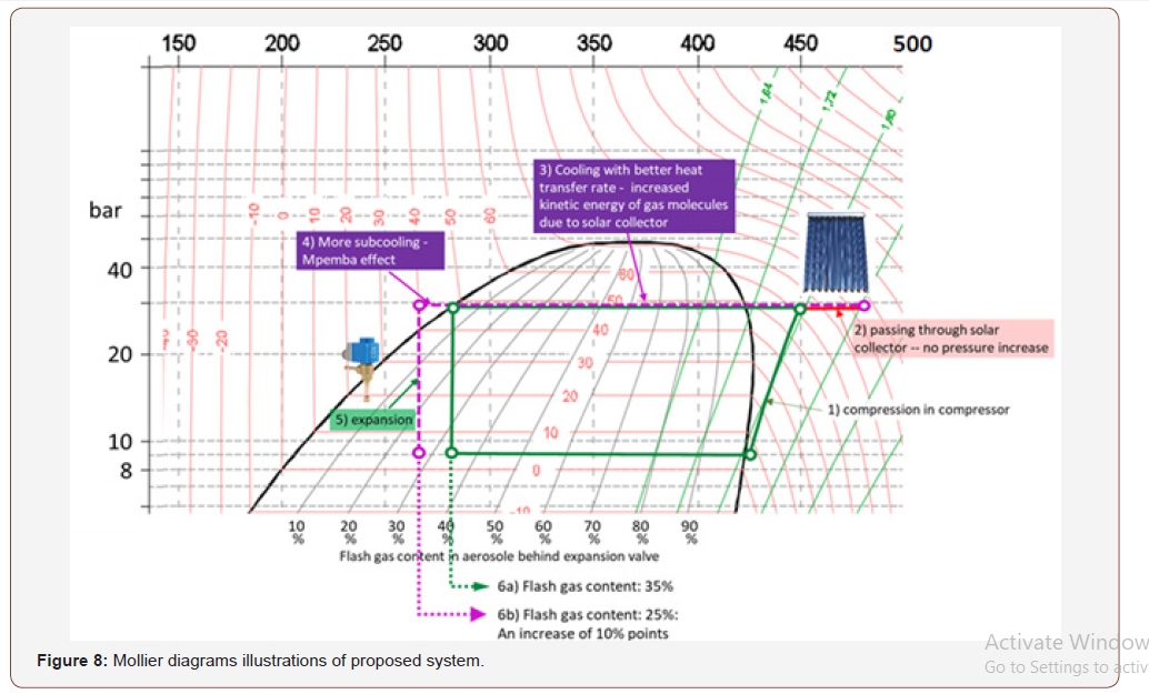
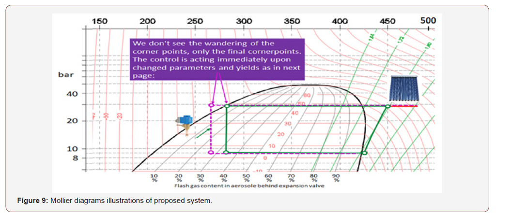
The below are a figure out and illustrations using Mollier diagrams which is a very common for systems with fixed compressor speed = fixed mass flow. DC Inverter units with variable mass flows and many changes in circuit offer wide range of mollier diagrams will be a high improvement for the proposed system (Figures 7-9).
Table 1:Spread sheet of applying the same equation in excel sheet (By author).

Acknowledgement
On leave from Total Quality Mangement, Gedeon Richter Plc.
Conflict of Interest
No conflict of interest.
References
- Yunus A Çengel, Afshin J Ghajar, Mc Graw-Hill (2011) Heat and Mass Transfer, Fundamentals and Applications. Fourth Edition,
- M Rathore (2010) Engineering heat and mass. University Science press 113, golden house, daryaganj, New delhi.
- M Thirumaleshwar (2006) Fundamentals of Heat and Mass transfer. Pearson Publication, India.
- RC Sachdeva (2009) Fundamentals of Engineering Heat and Mass transfer. New age international, pp. 674.
- Ron Zevenhoven, Åbo Akademi “University Thermal and Flow Engineering Laboratory”. Värme- ochströmningsteknik, Finland.
-
Ehab Nader T. Air Conditioning Booster. Glob J Eng Sci. 5(3): 2020. GJES.MS.ID.000612.
-
Solar radiation, R 134a, Thermodynamics, Momentum
-

This work is licensed under a Creative Commons Attribution-NonCommercial 4.0 International License.


