


 Research Article
A357 Aluminum Alloy Cutting Performance Finite Element Simulation
Received Date: April 14, 2021; Published Date: April 22, 2021
Abstract
Aiming at the problem that deformation caused by cutting force in the cutting process of A357 aluminum alloy, a two-dimension cutting simulation was established based on ABAQUS. The curves of chip, cutting force and stress under different cutting conditions were obtained by using Johnson-Cook constitutive equation. The finite element simulation was applied to further analyze the effects of different cutting conditions on chip, cutting force and stress. The simulation results show that the cutting force increases with the increase of cutting speed and increases with cutting depth in the experimental parameters range, it also leads to poor cutting quality. As the cutting length changes, the fluctuation of cutting force also increases and affects the overall quality of the workpiece.
Keywords: Finite element simulation; Cutting state; Cutting force
Introduction
Aluminum is very soft, and it has low strength and low density. When mixed with other metals, high strength aluminium alloys are formed, which can even surpass some high-quality carbon steels. Because of its good plasticity, electrical conductivity, thermal conductivity and resistance to metal corrosion, it is widely used in industry. Aluminum alloys are second only to steel in usage and range. It can be divided into deformed aluminium alloy and cast aluminium alloy by machining method. The comprehensive mechanical properties of deformed aluminum alloys are better than casting aluminum alloys. It can be processed into various shapes and specifications of profiles and mainly used in the manufacture of aviation equipment, automobile structures and doors and windows for the construction industry. Casting aluminum alloy can obtain the complex parts directly by casting process, so the processing cost can be reduced.
Over the past few decades, it has been found in machining processes that surface integrity includes surface roughness, residual stress, and microstructure, because it significantly affects the fa tigue life and corrosion resistance of the machined parts [1,2]. Machining parameters such as cutting conditions and tool geometry greatly affect the surface integrity characteristics [3]. The materials, tools, and equipment needed to conduct experimental tests are expensive, and the process of setting up tests is often time-consuming. Residual stress induced by cutting has been studied by many researchers through finite element modeling.
The Establishment of Finite Element Model
A357 constitutive model was established
The material constitutive model is used to describe the mechanical properties of materials and to characterize the dynamic response of materials during deformation. When the microstructure of the material is certain, the flow stress is significantly affected by deformation degree, deformation velocity, deformation temperature and other factors. Any change of these factors will cause a great change of flow stress. Therefore, the material constitutive model is generally expressed as the mathematical function relationship between flow stress and deformation parameters such as strain, strain rate and temperature. It is very important to establish the constitutive model of materials, not only in formulating reasonable processing technology, but also in studying the theory of metal plastic deformation. In modern plastic machining mechanics represented by plastic finite element, the flow stress of material is an important parameter when input and its accuracy is also the key to improve the reliability of theoretical analysis. In this research, the material constitutive model is a necessary prerequisite for numerical simulation of machining and an important basis for predicting the deformation of part milling. Only by establishing the stress-strain relationship with the change of strain rate and temperature under the condition of large deformation can the plastic deformation law of the material in the cutting process be accurately described and then the deformation size and trend of the parts can be predicted under the determined boundary conditions and the cutting load.
In the process of cutting, the workpiece deforms under high temperature and high strain, the time for the material being cut to become chips under the action of a tool is very short, and the strain, strain rate and temperature of the cutting layer are not uniformly distributed and the gradient varies greatly. Therefore, the constitutive equation which can reflect the influence of strain, strain rate and temperature on the flow stress of material is very important in cutting simulation. At present, the constitutive models of plastic materials commonly used are: Bodner-Paton, Follansbee-Kocks, Johnson-Cook, Zerrilli-Armstrong, etc. Only The Johnson-Cook model describes the thermoviscoplastic deformation behavior of materials at high strain rates. Johnson-cook model holds that materials exhibit strain hardening, strain rate hardening and thermal softening effects at high strain rates. Johnson-cook model is shown as follows [4]:

In the formula, the first item describes the strain strengthening effect of materials, the second item reflects the relationship between the flow stress and the increase of logarithmic strain rate, and the third item reflects the relationship between the flow stress and the exponential decrease of temperature Trrepresent the reference strain rate and the reference temperature respectively, Tm Is the melting point of the material. In the formula, A, B, n, C and m are five undetermined parameters; A, B and n represent the strain hardening term coefficients of materials; C represents the strain rate strengthening term coefficient of the material; m represents the thermal softening coefficient of material.
Material damage initiation criterion
In the finite element simulation process, chip separation is manifested as unit failure and separation problems, a rule is required for the degree to which the unit deforms before it separates. There are two kinds of separation criteria at present, one is to establish the geometric separation criterion of unit separation according to some geometric quantities and the other is based on some physical quantity, such as the stress and strain of the element in front of the tip during cutting. If the specified physical quantity exceeds the given value, unit separation is considered necessary.
In the previous work, it is found that this method has a disadvantage, it needs to define the shape of the cutter in advance to take it as the material flow boundary, but it is difficult to determine its parameters. As shown in Figure 1 below, due to the shape problem of the tool in the early stage, there was no chip, and all the failure elements were deleted.

The shear failure model is adopted in this paper to separate the chip from the workpiece. The shear failure model is based on the value of equivalent plastic strain at the integral point. When the damage parameter reaches 1, the element will fail. The failure parameters are defined as follows:

ω is the failure parameter,  lent plastic strain,
 is failure strain.
The Shear Damage model is adopted here to define the failure
strain.  is a function of the shear stress ratio and
strain rate:
is a function of the shear stress ratio and
strain rate: 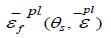 ,The shear stress ratio is defined as
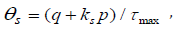 where q is the Mises equivalent stress, p
is the pressure stress, τmaxis the maximum shear stress and ks
is material parameter. At the same time, When defining temperature-
dependent material damage data, this article switches to data
with temperature [5].
where q is the Mises equivalent stress, p
is the pressure stress, τmaxis the maximum shear stress and ks
is material parameter. At the same time, When defining temperature-
dependent material damage data, this article switches to data
with temperature [5].
The Establishment of Geometric Model
Workpiece material parameters
The workpiece material is A357 aluminum alloy. The density is  the elasticity modulus is E = 79GP , poisson ratio is μ = 0.33, Other parameters are shown in the following table (Tables
1-5):
the elasticity modulus is E = 79GP , poisson ratio is μ = 0.33, Other parameters are shown in the following table (Tables
1-5):
Table 1:Chemical composition of A357.

Table 2:A357 thermal conductivity.

Table 3:A357 specific heat capacity.

Table 4:Linear expansion coefficient.

Table 5:A357 Johnson-Cook model material parameters.

Table 6:Simulation experiment scheme.

The establishment of geometric model
The two-dimension cutting finite element simulation model is shown in Figure 2, the approximate size is 10 and the size of the model workpiece is 2mm × 0.6mm , The front Angle of the prop is 70° and the back Angle is 5°. In this article, we define the plane cutting- edge swept as cutting plane, the plane cross cutting-edge and perpendicular to motion direction as base plane. The front Angle is dihedral angle between the front cutting surface and the base surface, the back Angle is dihedral angle between the back cutting surface and the In modeling, the workpiece is of two-dimensional plane deformable type and the tool is of analytic rigid body. Shell elements are used in Zhang Wei’s [6] model, A separate line is defined in the cutting process, that is the deformation cutting and the billet connection part. This model is not that complicated. It also can be used to simulate the temperature distribution in cutting process, but the separate line is not defined. Therefore, the analytical steps are dynamic, temperature-displacement and explicit. A split surface is set 0.11mm away from the upper surface of the workpiece to refine the mesh. The stable quadrilateral plane strain grid is adopted in mesh division of workpiece, the element type is the second - order precision four - node reduction integral thermal coupling element (CPE4RT), adaptive grid technology is used to partition and set the reference point in the upper right corner of the cutter. The cutting tool as the first surface, the cutting layer and adjacent parts as the second surface adopt the motion contact method, set the friction coefficient as 0.3. It is also different from Zhang Wei’s model. Define the lower surface of the workpiece and the side surface away from the tool as fully fixed. The cutting speed and boundary conditions of the defined tool reference point are uniformly distributed. The initial temperature of the cutting area is defined as room temperature 300K.
The simulation scheme
In this paper, single factor control method is used for simulation, only a single factor in cutting depth and cutting speed can be changed. The stress distribution curves of the cutting area under different working conditions are studied, the specific scheme is shown in Table 6.
Simulation Results and Analysis
Simulation results of different cutting speeds under the same cutting depth and contact length
When the cutting depth is 0.1mm, the contact length between the tool and the workpiece is 0.2mm, the two curves in the change curve represent the force on the X-axis and Y-axis of the tool respectively, it can be seen by comparing the curve of cutting force under different cutting speeds, The force on the tool in the vertical direction is slightly greater than that in the horizontal direction, The horizontal direction fluctuates less than the vertical direction, Therefore, this paper will discuss the change of force in the vertical direction. Because there is a sudden fluctuation in velocity at the initial moment, And the force on the end of the curve decreases, So the effective interval for comparing these curves is some time in the middle. The specific force changes in each case are discussed below.
• When the cutting speed was 7850mm/s, the Y-axis force was between 200N-400N, with small curve fluctuation and good surface quality, as shown in Figure 3, Figure 4.
• When the cutting speed was 8400mm/s, the Y-axis force was between 250N-600N, with small curve fluctuation and good surface quality, as shown in Figure 5, Figure 6.
• When the cutting speed is 8900mm/s, the force on the Y-axis is between 300N-600N, the curve fluctuates greatly, and the cut surface quality is poor, as shown in Figure 7, Figure 8.
• When the cutting speed is 9450mm/s, the Y-axis force is between 300N-600N, the curve fluctuates greatly, and the cut surface quality is poor, as shown in Figure 9, Figure 10.
• When the cutting speed is 9950mm/s, the Y-axis force is between 300N-700N, the curve fluctuates greatly, and the cut surface quality is poor, as shown in Figure 11, Figure 12.
• When the cutting speed is 10450mm/s, the force on the Y-axis is between 400N-750N, the curve fluctuates gently, and the cut surface quality is poor, as shown in Figure 13, Figure 14;


It can be seen from the force analysis of each curve that the force decreases with the change of velocity, then increases from small to large, and then decreases again. On the whole, the force fluctuation is relatively stable, and the smaller speed is at 7850mm/s and 8400mm/s cutting speed. The final velocity is set at 7850mm/s according to the machined surface quality.
Simulation results of different cutting depth at the same cutting speed and contact length
At a cutting speed of 7850mm/s, the contact length was 0.2mm, it can be seen that the cutting force is increasing in the simulation of the cutting process at different cutting depths and the curve of cutting force changing with time. The contents are as follow:
• When the depth is 0.08mm, the force on the Y-axis is between 150N-500N, the curve fluctuates greatly, and the surface quality after the resection is good, as shown in Figure 15, Figure 16;
• When the cutting depth is 0.1mm, the force on the Y-axis is between 200N-400N, the curve fluctuates gently, and the surface quality after cutting is good, as shown in Figure 3, Figure 4;
• When the cutting depth is 0.12mm, the Y-axis forces between 250N-550N, the curve fluctuates greatly and the surface quality is good, as shown in Figure 17, Figure 18;
• When the cutting depth is 0.14mm, the Y-axis forces between 300N-600N, the curve fluctuates greatly, and the surface quality is general, as shown in Figure 19, Figure 20;
• When the cutting depth is 0.16mm, the Y-axis forces around 300N-8000N, the curve fluctuates greatly, and the surface quality is general, as shown in Figure 21, Figure 22;
It can be seen from the force analysis of each curve that the force decreases with the change of cutting depths, then increases from small to large, and then decreases again. On the whole, Under the cutting depth of 0.1mm and 0.12mm, the force fluctuation is relatively stable and small. The final cutting depths is set at 0.1mm according to the machined surface quality .


Simulation results of different contact lengths at the same cutting speed and cutting depth
At a cutting speed of 7850mm/s and a cutting depth of 0.1mm, the drawing of cutting process and the curve of cutting force changing with time are simulated for different cutting contact lengths. It can be seen from the curve that the cutting force is increasing with the increase of contact length, and the details are as follows:
• When the contact length is 0.15mm, the Y-axis force is between 100N-500N, the curve fluctuates gently, and the surface quality after the resection is poor, as shown in Figure 23, Figure 24;
• When the contact length is 0.2mm, the Y-axis force is between 200N-400N, the curve fluctuates gently, and the surface quality after the resection is good, as shown in Figure 3, Figure 4;
• When the contact length is 0.25mm, the force on the Y-axis is between 150N-400N, the curve fluctuates greatly, and the surface mass after the resection is poor, as shown in Figure 25, Figure 26;
• When the contact length is 0.30mm, the Y-axis forces around 150N-400N, the curve fluctuates greatly, and the surface quality after resection is poor, as shown in Figure 27, Figure 28;


From the perspective of cutting force fluctuation and machining quality surface, the longer the cutting length is, the greater the influence of force on the overall quality of the workpiece is. Appropriate reduction of cutting length can ensure the overall quality of the workpiece.
Conclusion
In this paper, the high speed cutting of aluminum alloy is studied and analyzed by finite element two-dimensional cutting simulation model. The simulation was carried out with different cutting speeds, cutting depth and cutting length. The distribution of the workpiece in the elastic-plastic stress field is known, and the variation of the cutting force and the workpiece surface quality with the cutting speed, cutting length and cutting depth is obtained, conclusions are as follows:
• The cutting speed has significant influence on the cutting force and cutting quality. When the cutting speed is kept at a low level, the cutting force fluctuation is not very great. But with the increase of speed, the fluctuation degree of cutting force will increase, and the cutting quality will also become worse.
• The influence of cutting depth on cutting force is also very obvious, With the increase of cutting depth, the cutting force increases and high degree of fluctuation; The impact on the quality of the cutting, from the cutting surface, or more rough.
• The cutting length has obvious influence on the cutting force. As the cutting length increases, the cutting force increases slightly. From the cutting quality, the cutting surface is relatively smooth, the impact is not very big.
In general, in order to ensure good cutting quality, the cutting speed can be reduced appropriately, try to control within 8m / s , the overall impact on the workpiece is not big
Acknowledgement
Many thanks to my supervisor Prof. Jiujiang Zhu for his help and financial support through the project “High Education funding of Guangdong Province: 2018KZDXM072”. This research is part of the postgraduate demo course project of Wuyi University (YJSFSKC- 17-01).
Conflict of Interest
None.
References
- Javidi A, Rieger U, Eichlseder W (2008) The effect of machining on the surface integrity and fatigue life. International Journal of Fatigue 30(10-11): 2050-2055.
- Sadeghifar M, Sedaghati R, Jomaa W, Songmene V (2018) A comprehensive review of finite element modeling of orthogonal machining process: chip formation and surface integrity predictions. The International Journal of Advanced Manufacturing Technology 96.
- Touazine H, Chadha K, Jahazi M, Bocher P (2019) Characterization of Subsurface Microstructural Alterations Induced by Hard Turning of Inconel 718. Journal of Materials Engineering and Performance 28.
- Ben M, Stephen A Batzer, G Ivan M (2002) A numeric investigation of the rake face stress distribution in orthogonal machining. Journal of Materials Processing Tech 123(1): 114-119.
- Liu Jiafu, Zhang Hongcai, Qi Junhong (2006) Finite Element Analysis of Two-dimensional Metal Cutting Based on ABAQUS.Mechanical Design and Manufacturing.
- Zhang Wei (2015) Finite Element Simulation and Analysis of High Speed Cutting Process of Two Typical Metals, Liaoning Technical University.
-

This work is licensed under a Creative Commons Attribution-NonCommercial 4.0 International License.


