 Review Article
A Rule Based Method to Construct The Mohr’s Circle for Plane Stress
Swami Karunamoorthy*
Department of Mechanical Engineering & Materials Science, Washington University in St. Louis Saint Louis, Missouri
Swami Karunamoorthy, Department of Mechanical Engineering & Materials Science, Washington University in St. Louis Saint Louis, Missouri.
Received Date: November 15, 2019; Published Date: November 20, 2019
Abstract
Mohr’s Circle is a graphical representation of the state of plane stress at a point. It is an important concept to learn for the understanding of plane stress transformation. However, it remains a challenge for both engineering as well as engineering technology students to understand the principles of Mohr’s Circle. In this paper, an emphasis is given to identify the source of pedagogical difficulty and a simple rule-based method is presented as a new approach for effective teaching as well as learning. It is a viable method to understand the Mohr’s Circle and its application to plane stress transformation.
Introduction
The topic on Plane Stress or Stress Transformation is introduced in a course on Mechanics of Solids or Mechanics of Materials or Strength of Materials at junior level for the undergraduate students in engineering or technology programs. The sign convention for the normal stress is well understood that tensile stress is positive and compressive stress is negative. The shear stress on an element is described as positive if the right diagonal stretches as shown in Figure 1(a).
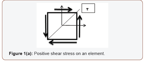

Similarly, if the left diagonal stretches as shown in Figure 1(b), the shear stress on an element is considered as negative.
However, additional sign conventions are required to draw the Mohr’s Circle [1] and they are not unique. Different textbooks adopt different sign conventions for the shear on each plane (or face) of the element. Several textbooks are used as comparison for this purpose.
Nomenclature
• A1 – Top plane on the element • B1 – Adjacent plane (90° counterclockwise to A1) • A2 – Bottom plane on the element • B2 – Adjacent plane (90° counterclockwise to A2) • X-Y Reference axes • X1-Y1 New position of reference axes after rotation • σ – Normal stress • σ1, σ2 – Principal stresses • τ – Shear stress • ϴ - Arbitrary angle of rotation • ϴp – Principal angleAnomaly Among Textbooks
In Reference [1], the author states, “To employ Mohr’s circle, we must set forth additional sign conventions. A shear stress will be taken as positive on a face (A1) of an element in regard to Mohr’s circle when it yields a clockwise moment about the center point at the element. A shear stress yielding a counterclockwise moment (B1) about the point will then be taken as negative.” It is shown in Figure 2.
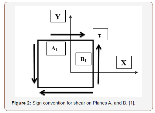
This method creates a conflict with conventional method for moment based on right hand thumb rule. Based on this rule, counterclockwise moment is positive and clockwise moment is negative. For a student it results in a dilemma of Clockwise or Counterclockwise? Which one results in positive moment? However, this method for Mohr’s circle [1-3] leads to correct solution while it is a pedagogical challenge for an instructor to teach something that is opposite of right-hand thumb rule. Also, it is a challenge in learning for a student
In Reference [4], the author states, “An alternative sign convention for shear stresses is sometimes used when constructing Mohr’s circle. Instead of thinking of the vertical axis as having negative shear stresses plotted upward and positive shear stresses plotted downward (which is a bit awkward), we can think of the vertical axis as having clockwise shear stresses plotted upward and counterclockwise shear stresses plotted downward.” It is given in Figures 3(a) & 3(b).
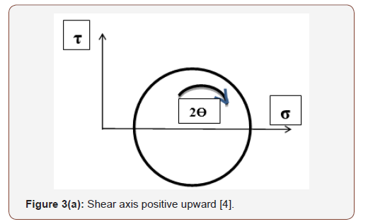
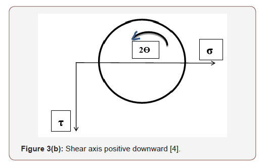
If the shear axis is positive upward, clockwise is considered as positive while if the shear axis is positive downward, counterclockwise is considered as positive. Again, it is conceptually correct; however, it is a challenge in learning to a student.
In Reference [5], the shear stress is assumed positive in the positive y & y’-directions as shown in Figures 4(a) & 4(b).
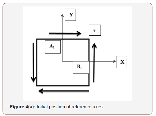
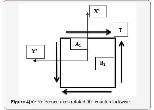
Based on this assumption, the shear stress on Plane-B1 is positive since it is acting along positive Y-direction as shown in Figure 4(a); while the shear stress on Plane-A1 is negative since it is acting along negative Y’-direction as shown in Figure 4(b). The X-Y axes are rotated by 90° counterclockwise to X’-Y’ axes to justify the sign of shear stress. The author states, “In other words, a rotation ϴ of the X’ axis on the element will correspond to a rotation 2ϴ on the circle in the same (counterclockwise) direction.” This is true for considering τ-axis positive downwards in the construction of Mohr’s circle. The author adds, “If instead the τ-axis were constructed positive upwards, then the angle 2ϴ on the circle would be measured in the opposite direction to the orientation ϴ of the X’ axis.” Although this approach leads to correct transformation of stresses, it is a challenge in learning and comprehension of Mohr’s circle.
In Reference [6], the author does not distinguish positive or negative shear stress; however he states, “If the shear stress acting on a face of the stress element tends to rotate the stress element in a clockwise direction, then the shear stress is plotted above the σ-axis. If the shear stress tends to rotate the stress element in a counterclockwise direction, then the shear stress is plotted below the σ-axis.” This method eliminates the need for whether τ-axis should be positive upward or downward. Absolute values of shear stress with subscripts of ‘cw’ or ‘ccw’ (τcw, τccw) is plotted above or below the σ-axis. Similar treatment on sign convention is encountered in Ref [7-13]. All these approaches lead to challenges in learning the concept especially to an undergraduate student in both engineering and technology programs.
Rule Based Method
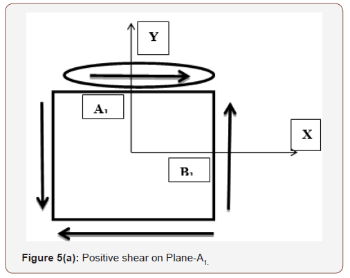
Let us assume a shear is applied on top plane A1 in the positive x-direction as shown in Figure 5(a). For force equilibrium, an equal and opposite shear is applied on bottom plane. For moment equilibrium a shear couple is applied on right plane (B1) and left plane.

Since the applied shear on Plane A1 is in the positive x-direction, it is intuitive to assume this shear is positive. The shear on adjacent plane B1 (90° counterclockwise to A1) is applied to counter the moment action of shear on plane A1. So, the sign of shear on plane B1 is negative of the sign of shear on plane A1. Therefore, if the shear on plane A1 is positive as shown in Figure 5(a), the shear on plane B1 is negative. Similarly, if the shear on Plane A1 is negative as shown in Figure 5(b), the shear on Plane B1 is positive. Although there are four planes (Top, Bottom, Right and Left) with given shear, the sign can be determined by observing the direction of shear on Top Plane alone. Therefore, a set of rules can be developed for the sign convention of shear as given below:
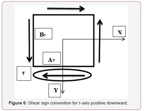
With reference to Figure 6, the shear on Plane A2 is negative since it is acting in the negative direction of X-axis, and hence the shear on plane B2 is positive. To construct a Mohr’s circle, a diameter is required and to draw the diameter the coordinates of two end points of the straight line is required. If the shear axis is positive upwards, apply the rules on Planes A1 and B1 to find the stress coordinates for Mohr’s circle diameter. If the shear axis is positive downwards, apply the rules on Planes A2 and B2.
Mohr’s Circle
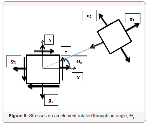
Mohr’s circle is a graphical representation of the given state of plane stress on an element. If the element is rotated through an angle ϴ, the resulting new stresses on the element can be easily obtained from the Mohr’s circle. This stress transformation is shown on the rotated element in Figure 7. If the element is rotated through an angle equivalent to the principal angle ϴp, the shear stress on the element vanishes while the normal stresses would be equivalent to maximum and minimum value of stresses known as principal stresses. This is shown in Figure 8 for an element rotated through an angle equivalent to principal angle.

In the construction of a Mohr’s circle we are plotting the normal and shear stress values on two adjacent planes of a stress element. The graph has normal stress along the horizontal axis and shear stress along the vertical axis. In general, horizontal axis is positive to the right and vertical axis is positive upwards. If we have the stress values on two adjacent planes (A1-B1
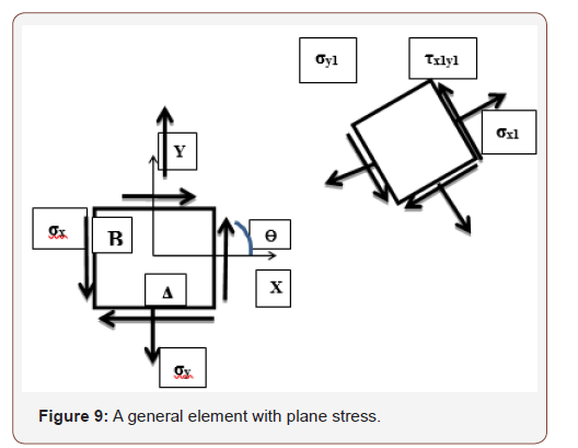
) as coordinates, they can be represented on the graph as a diameter of the circle. With this diameter on the graph, a circle can be easily constructed. The rules 1, 2, & 3 help to determine these coordinates easily without any ambiguity. If the shear axis is chosen as positive downward, the rules can be easily applied for stresses on Planes A2-B2, to determine the appropriate coordinates.For construction of Mohr’s circle, the state of stress on an element is given in Figure 9. The stress coordinates on each plane is given below:
Plane A1: (σy, τxy)
Plane B1: (σx, - τxy).
Plane A2: (σy, - τxy)
Plane B2: (σx, τxy).
Example
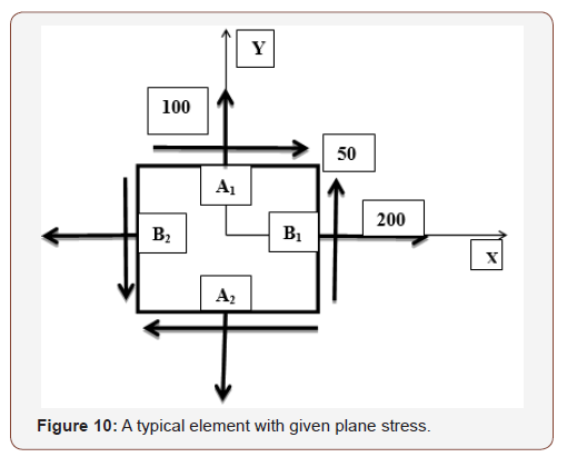
To illustrate the application of rule-based method, an example problem [14] is given below in Figure 10.
σx = 200 psi, σy = 100 psi, τxy = 50 psi
The normal stresses are tensile stresses and hence they are positive. The shear stress on the element is positive because the shear on Plane A1 is acting in the positive X-direction (Rule 1). The Mohr’s circle is constructed with the shear axis positive upwards as well as positive downwards.
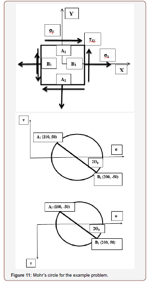
To construct a Mohr’s circle with the shear axis positive upwards, the stress information on Planes A1 and B1 are:
A1 (100, 50); B1 (200, -50)
To construct a Mohr’s circle with the shear axis positive downwards, the stress information on Planes A2 and B2 are:
A2 (100, -50); B2 (200, 50)
The Mohr’s circle is presented in Figure 11.
Impact on Education
The method from traditional textbooks was used for several years in teaching Mohr’s circle and about fifty percent of students understood the concept. In the last few years, the rule-based method was used in the classroom resulting in remarkable improvement in understanding the concept. About ninety five percent or above students did well in the test on Mohr’s circle.
Conclusion
The construction of Mohr’s circle has been presented by several different methods by different authors in the literature. Although all the methods lead to correct stress transformation, it is a pedagogical challenge to present it in such a way that students can learn effectively in both engineering and technology programs. The primary challenge is to define the shear on each plane of the stress element without any ambiguity. A simple rule-based method is presented in this article to account for the shear and determine the coordinates for constructing the Mohr’s circle. This method eliminates the need to know whether the shear rotate the element in clockwise or counterclockwise direction. The example problem illustrates the application of the rules and demonstrates the process for easy construction of Mohr’s circle. The student performance showed significant improvement based on learning by “Rule-Based” method compared to the traditional methods from the textbooks. The rule-based method is a viable approach for effective learning of stress transformation and understand the principles of Mohr’s circle.
Acknowledgement
None.
Conflict of Interest
No conflict of interest.
References
- McGill HC Jr, McMahan CA, Zieske AW, Sloop GD, Walcott JV, et al. (2000) Associations of coronary heart disease risk factors with the intermediate lesion of atherosclerosis in youth. The Pathobiological Determinants of Atherosclerosis in Youth (PDAY) Research Group. Arterioscler Thromb Vasc Biol 20(8): 1998-2004.
- Baker JL, Olsen LW, Sørensen TI (2007) Childhood body-mass index and the risk of coronary heart disease in adulthood. N Engl J Med 357(23): 2329-2337.
- Raitakari OT, Juonala M, Rönnemaa T, Keltikangas Jarvinen L, Rasanen L, et al. (2008) Cohort profile: the cardiovascular risk in Young Finns Study. Int J Epidemiol. 37(6): 1220-1226.
- Silva LR, Stefanello JM, Pizzi J, Timossi LS, Leite N (2012) Atherosclerosis subclinical and inflammatory markers in obeseand nonobese children and adolescents. Rev Bras Epidemiol 15(4): 804-816.
- El Jalbout R, Cloutier G, Roy Cardinal MH, Henderson M, Lapierre C, et al. (2018) Carotid artery inima media thickness measurement in children with normal and increased body mass index: a comparison of three techniques. Pediatric radiology 48(8): 1073-1079.
- Raitakari OT, Juonala M, Kahonen M, Taittonen L, Laitinen T, et al. (2003) Cardiovascular risk factors in childhood and carotid artery intima-media thickness in adulthood: The Cardiovascular Risk in Young Finns Study. JAMA 290(17): 2277-2283.
- Dalla Pozza R, Ehringer Schetitska D, Fritsch P, Jokinen E, Petropoulos A, et al. (2015) Intima media thickness measurement in children: a statement from theAssociation for European Paediatric Cardiology (AEPC) Working Group on cardiovascular prevention endorsed by the Association for European Paediatric Cardiology. Atherosclerosis 238(2): 380-387.
- Touboul PJ, Hennerici MG, Meairs S, Adams H, Amarenco P, et al. (2012) Mannheim carotid intima-media thickness and plaque consensus (2004-2006-2011): an update on behalf of the advisory board of the 3rd and 4th watching the risk symposium 13th and 15th European Stroke Conferences, Mannheim, Germany, 2004, and Brussels, Belgium, 2011. Cerebrovasc Dis 34(4): 290-296.
- Doyon A, Kracht D, Bayazit AK, Deveci M, Duzova A, et al. (2013) Carotid artery intima-media thickness and distensibility in children and adolescents: reference values and role of body dimensions. Hypertension 62(3): 550-556.
- Jourdan C, Wuhl E, Litwin M, Fahr K, Trelewicz J, et al. (2005) Normative values for intima-media thickness and distensibility of large arteries in healthy adolescents. J Hypertens. 23(9): 1707-1715.
- Engelen L, Ferreira I, Stehouwer CD, Boutouyrie P, Laurent S (2013) Reference Values for Arterial Measurements C. Reference intervals for common carotid intima-media thickness measured with echotracking: relation with risk factors. Eur Heart J 34(30): 2368-2380.
- Bohm B, Hartmann K, Buck M, Oberhoffer R. (2009) Sex differences of carotid intima-media thickness in healthy children and adolescents. Atherosclerosis 206(2): 458-463.
- Neri S, Signorelli SS, Scuderi R, Bruno M, Bertino G, et al. (2011) Carotid intima-media thickness and liver histology in hemodialysis patients with nonalcoholic Fatty liver disease. Int J Angiol 20(3): 149-156.
- Ried Larsen M, Grontved A, Moller NC, Larsen KT, Froberg K, et al. (2014) Associations between objectively measured physical activity intensity in childhood and measures of subclinical cardiovascular disease in adolescence: prospective observations from the European Youth Heart Study. Br J Sports Med 48(20): 1502-1507.
- Sass C, Herbeth B, Chapet O, Siest G, Visvikis S, et al. (1998) Intima-media thickness and diameter of carotid and femoral arteries in children, adolescents and adults from the Stanislas cohort: effect of age, sex, anthropometry and blood pressure. J Hypertens 16(11): 1593-1602.
- Stein JH (2009) Carotid ultrasound in children: a window to arterial ageing. Heart 95(8): 611-612.
-
Swami Karunamoorthy. A Rule Based Method to Construct The Mohr’s Circle for Plane Stress. Glob J Eng Sci. 4(2): 2019. GJES. MS.ID.000581.
-
Top plane on the element, Adjacent plane, Reference axes, Mohr’s circle, Plane stress
-

This work is licensed under a Creative Commons Attribution-NonCommercial 4.0 International License.


