 Research Article
Increasing The Range Afforded by A MIMO System Compared to A Single-Input Single-Output (SISO) System
Ala Eldin Abdallah Awouda*
Bisha University College of Engineering Electrical Engineering Department, Bisha, KSA
College of Engineering, Sudan University of Science and Technology, Khartoum, Sudan
Ala Eldin Abdallah Awouda, Bisha University College of Engineering Electrical engineering department, Bisha, KSA & College of Engineering, Sudan University of Science and Technology, Khartoum, Sudan
Received Date: October 20, 2022; Published Date: November 18, 2022
Abstract
The ability of Multi-Input Multi-Output (MIMO) antenna systems to increase the capacity of Wi-Fi based outdoor links has been studied extensively. MIMO can also be used to increase transmission distance for a fixed data rate, a fact that is of great practical importance. This paper studies the distance increase as a function of the desired data rate. Plots of the rate as a function of distance for MIMO systems with different numbers of antennas has been provided, as well as for Single-Input Multiple-Output (SIMO) , Multiple -Input Single-Output (MISO) and Single-Input Single-Output (SISO) systems as a reference. The results are produced by evaluating a well-known MIMO capacity formula where the average SNR is computed using Green-Obaidat propagation loss models.
Introduction
The IEEE 802.11 technology has been implemented to provide various network services, for example, home and personal applications, internet hotspot service and bridge for different wired or wireless networks. Another implementation is Wi-Fi based long distance networks, the unlicensed Wi-Fi spectrum and a variety of commodity IEEE 802.11 hardware make Wi-Fi an attractive communication method because of its wide availability and low cost, however, extending the range is one of the main issues that faces this networks, one of the technologies that help solving this problem is MIMO.
Much of discussion of MIMO revolves around its remarkable ability to increase the capacity of the system in proportion to the number of antennas being used, by performing spatial multiplexing. While capacity is a key performance measure of wireless systems, a no less important measure is the range of the communication link over which communications at a specified data rate can be sustained. It is generally understood that increased capacity can be traded off against increased range. In other words, instead of using the MIMO system to its full capacity it can be operated at a lower data rate, and a correspondingly lower required signal-to-noise ratio (SNR), which means a longer range. However, somewhat surprisingly few specific results on this important issue seem to be available. SISO Antenna Technique is the oldest known type of configuration. There is only a single antenna working as a transmitter and a single antenna working as a receiver. In SIMO Antenna Technique, one antenna transmits and multiple receive antennas, the system is known as Single input Multiple-output (SIMO).
In the MISO (Multiple-input Single-output) antenna technique, multiple antennas are used in the transmitter while a single antenna is used in the receiver. It is a comparatively new technology. When using MIMO technology, multiple receiving and transmitting antennas are used to increase capacity without additional power or bandwidth. The capacity scales linearly with the minimum number antennas used at the transmitter or the receiver. The MIMO design of a communications link can be classified in these two ways. MIMO using diversity techniques and MIMO using spatial-multiplexing techniques. Both of these techniques are used together in MIMO systems.
Free space propagation model is used to predict the signal strength at the receiving node when there is a clear Line of Sight (LOS) path between the transmitting and the receiving node.

Where Pt represents the transmit power (watts), λ is the wavelength of radiation (m), and L is the system loss factor which is independent of propagation environment. The system loss factor represents overall attenuation or loss in the actual system hardware, including transmission line, filter, and antennas. In general, L > 1, but L = 1 if we assume that there is no loss in the system hardware. It is obvious that the received power attenuates exponentially with the distance d.

In fact, a more generalized form of the path loss model can be constructed by modifying the free-space path loss with the path loss exponent n that varies with the environments. This is known as the log-distance path loss model, in which the path loss at distance d is given as

Where d0 a reference distance at which or closer to the path loss is inherits the characteristics of free-space loss in Equation (3.3). As shown in Table 1, the path loss exponent can vary from 2 to 6, depending on the propagation environment. Note that n=2 corresponds to the free space. Moreover, n tends to increase as there are more obstructions [1-3].
Table 1:Path loss exponent.

Capacity of a SISO Channel
All system designs strive for a target capacity of throughput. For SISO channels, the capacity is calculated using the well-known Shannon equation. Shannon defines capacity for an ergodic channel that data rate which can be transmitted with asymptotically small probability of error. The capacity of such a channel is given by in terms bits/sec/Hz.

This capacity is based on a constant data rate and is not a function of whether channel state information is available to the receiver or the transmitter. This result is applicable only to ergodic channels, ones where the data rate is fixed, and SNR is stable.

The Capacity of a MIMO Channel
Compared to a conventional single antenna system, the channel capacity of a multiple antenna system with NT transmit and NR receive antennas can be increased by the factor of min (NT, NR) without using additional transmit power or spectral bandwidth. Figure 3 shows a schematic overview of a MIMO system.
Consider a Mt×Mr MIMO system with Mt transmit antennas and Mr receive antennas. Let H denote the channel matrix relating the vector of transmitted signals to the vector of received signals. Assuming that the channel state is unknown at the transmitter, it is well-known that the capacity of this system for a fixed H is given by
C=log det (I+H SNR/Mt)
The Figure 3 show the comparison of SISO and MIMO systems using the same power. MIMO capacity increases linearly with the number of antennas, where SISO/SIMO/MISO systems all increase only logarithmically [4].
Simulation
Figure 1:Green-Obaidat path-loss Model.
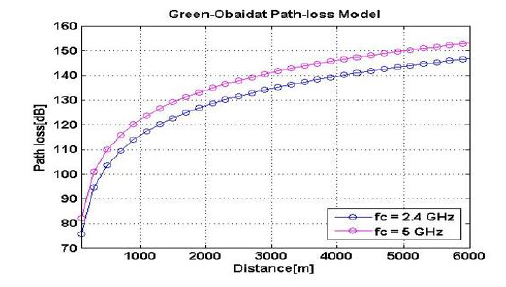
One of equation parameter is carrier frequency, which in 802.11n Wi-Fi standard have two values, 2.4 GHz & 5 GHz. The path loss was computed for each frequency and plotted with distance values. Plotting the path loss PL(D) vs. distance with two available values for frequency allow us to evaluate the effect of changing the frequency to the path loss.
For a given distance (D), the average SNR was evaluated.
Channel Bandwidth is one of the SNR parameters, which also have
two values in 802.11n Wi-Fi standard, 20 MHz & 40MHz, due to
this; the SNR values was evaluated in four cases:
• Using 2.4 GHz frequency with 20 MHz Bandwidth.
• Using 2.4 GHz frequency with 40 MHz Bandwidth.
• Using 5.0 GHz frequency with 20 MHz Bandwidth.
• Using 5.0 GHz frequency with 40 MHz Bandwidth.
The capacity is then evaluated vs. distance functions for MIMO systems with different numbers of transmit and receive antennas and with the different cases of computed SNR, A numerical results will be presented, to evaluate the SNR values with the increasing distance and to examine the effect of MIMO technology in increasing the capacity and data rate for a given distance [5].
Numerical analysis and Discussion
Figure 2 illustrate the variations of path loss values in 802.11n frequencies with increasing distance. The result of comparison shows that the value of path loss at frequency 2.4 GHz is equal to 144 dB and the value of path loss at frequency 5 GHz is equal to 150dB. From the result the value of using 2.4GHz has path loss less than 5GHz.
Figure 2:Variation of SNR with increasing distances a) Fc = 2.4 GHz b) Fc = 05GHz.
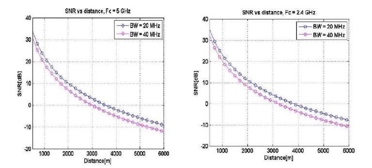
From Table 2 the value of SNR is at highest value when using 2.4GHz frequency and 20MHz Bandwidth.
Figure 3 illustrate the variations of capacity with increasing distances for a single antenna system, and multiple antenna systems, we can notice the variation with the four cases of SNR values that was mentioned in the previous section. Comparison between different capacity values at 5Km distance is done and the result is shown in Table 3 below.
Figure 3:Capacity vs. distance for SISO and MIMO antenna system for a) Case 1 b) Case 2 c) Case 3 d) Case 4.
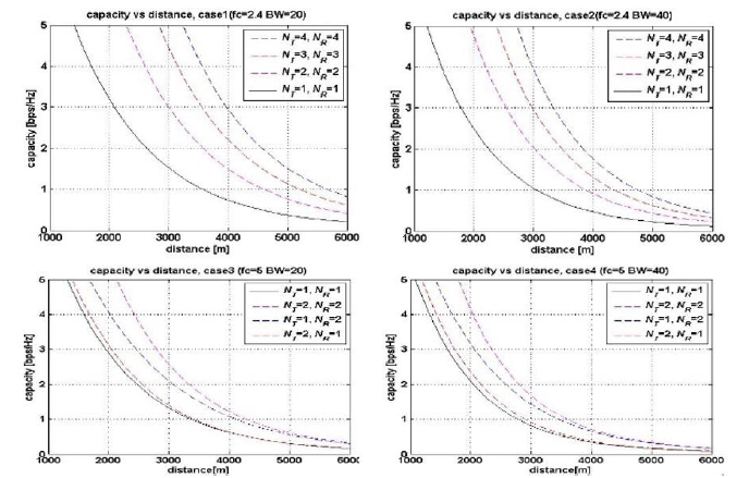
Table 2:SNR cases.

Table 3:Capacity values for SISO and MIMO systems at 5 km..

A number of observations can be made from the Figure 3 and the Table 3 above. The highest values of capacity can be obtained by using the parameter in Case 1. As expected, the range increase for the 4 × 4 MIMO system is significantly larger than for the 3×3and 2 × 2 system. In Figure 3(a) for example, when operating at a capacity of 1 bits/sec/Hz we have ranges of 3700 meters, 4600 meters , 5200 meters and 5600 meters respectively, for SISO, 2 × 2 MIMO, 3 × 3 MIMO and 4 × 4 MIMO [6].
Figure 4 shows the variations of capacity with increasing distances for SISO, SIMO, MISO and MIMO antenna systems, we can notice the variation with the four cases of SNR values that was mentioned in the section above. We compared the capacity values at 5Km distance, and the result is shown in Table 4 below. From Figure 4 and Table 4 we can notice that the range of the MIMO system is always greater than that of the SIMO system, but the SIMO system captures a significant part of the range improvement relative to the SISO reference system. Moreover, in Figure 4(a) for example, when operating at a capacity of 1 bits/sec/Hz we have ranges of 3600 meters, 3700 meters 4400 meters, and 4450 meters respectively, for SISO, MISO, SIMO and MIMO.
Figure 4:Capacity vs. distance for SISO, SIMO, MISO and MIMO antenna system for a) Case 1 b) Case 2 c) Case 3 d) Case 4.
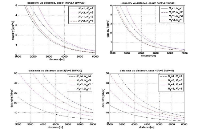
Table 4:Capacity values for SISO, SIMO, MISO and MIMO systems at 5 km.

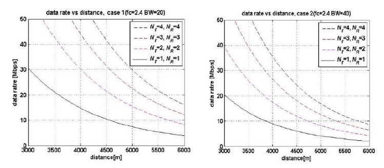
Figure 5 illustrate the variations of data rate with increasing distances for a single antenna system, and multiple antenna systems, we can notice the variation with the four cases of SNR values that was mentioned in the section above. We compared the data rate values at 5Km distance, and the result is shown in Table 5 below.
Table 5:Data rate values for SISO and MIMO systems at 5 km.

From Figure 5 and Table 5 we can observe that the data rate is descending clearly with increasing the distance. Moreover, the highest values of data rate can be obtained by using the parameter in Case 1.
Figure 5:Data rate vs. distance for SISO and MIMO antenna system for a) Case 1 b) Case 2.
Conclusion
MIMO technology is being incorporated into wireless systems to increase capacity and distance. In this work we examined the ability of MIMO to increase distance for a given system capacity. It is shown that significant coverage increase can be achieved by MIMO systems with relatively small numbers of antennas. It should be noted that SIMO, while clearly inferior to MIMO, capture a significant part of the range improvement of MIMO. The analysis presented in this work is based entirely on the theoretical capacity equation and does not take into account the inevitable implementation losses in MIMO systems. These include issues such as capacity loss due to channel estimation. These implementation losses may reduce significantly the range increase of MIMO systems from the values predicted using theoretical capacity equation.
Acknowledgement
None.
Conflict of Interest
There is no conflict of interest.
References
- GJ Foschini, MJ Gans (2002) Capacity of MIMO systems based on measured wireless channels. IEEE J Select. Areas Commun 20(3): 561-569.
- (2021) Wi-Fi Generation Numbering. Electronic Notes.
- Chirag R Shah (2017) Performance and Comparative Analysis of SISO, SIMO, MISO, MIMO. International Journal of Wireless Communication and Simulation. Research India Publications 9(1): 1-14.
- Kritika Sengar, Nishu Rani, Ankita Singhal, Dolly Sharma, Seema Verma, et al. (2014) Study and Capacity Evaluation of SISO, MISO and MIMO RF Wireless Communication Systems. International Journal of Engineering Trends and Technology (IJETT). 9(9).
- RV Durga, A Mc Lauchlin (2021) Performance analysis of MIMO system capacity with various receiver architectures. Int J Grid Distrib Comput 13(2): 2598-2608.
- X Sun, P Xu (2015) Analysis on channel capacities of wireless MIMO systems Comput. Telecommun 7: 35-42.
-
Ala Eldin Abdallah Awouda*. Increasing The Range Afforded by A MIMO System Compared to A Single-Input Single-Output (SISO) System. Glob J Eng Sci. 10(3): 2022. GJES.MS.ID.000737.
-
Multi-Input, Multi-Output, MIMO, Single-Input, Single-Output, SISO, Line of Sight, Free space
-

This work is licensed under a Creative Commons Attribution-NonCommercial 4.0 International License.


