 Review Article
HVAC Automatically Controlled by Motor Control Center
Syed Adeel Ahmed Shah*
Mechanical Department, National University Science & Technology, Muscat, Oman
Syed Adeel Ahmed Shah, Mechanical Department, National University Science & Technology, Muscat, Oman.
Received Date:July 25, 2022; Published Date:July 28, 2022
Abstract
Motor control serves to control the devices or a collection of devices in a particular and programmed manner for the betterment and the performance of the motor. Motor control is either automatic or manual which depends on the function of starting or stopping the motor. The motor control also determines factors like protecting against overloads and fault also the regulation or limiting the torque. Electric motor of any kind required a certain kind of controller. So, the motor controller will be performing different task on the variant features and the complexity of the task. The motor control center comprises of a common power bus and motor control units. The motor control center manages HVAC system in the industry applications, the basic concept of the motor control center is to control an entity which is temperature in this project. To start designing the whole panel was constructed in AutoCAD. The two motors which will be used in the Motor Control Centre are going to be star delta and DOL (direct online).Further the whole study of the motor control center and developing the link with the sensor to control the heat ventilation air condition system is the main aim of the project. The study of Heat Ventilation Air Condition system and the temperature to be controlled automatically by the help of motor control center with the help of sensor was achieved. The test was conducted by manually and automatic control for the betterment of the project. By studying and developing the link of HVAC system with the Motor control center with the help of sensor gave a deeper knowledge of the industrial applications related to it and the scope of controlling the temperature with other sensors and regulation of temperature control on wide spectrum.
Keywords:HVAC; Motor control center; Direct online motor; Star delta motor; Sensor; Motor control
Introduction
For motor control the main constituent is a MCC (motor control center) which is an assembly of one or more enclosed sections consuming a common power bus apart from that the motor control center consist of containing motor control units. In modern era, motor control center is a factory assembly of several motor starters. The main concept of a motor control center is to control primarily the distribution of the power to electric motors. This further includes programmable controllers, variable frequency drives, and metering. Motor control centers (MCC) are generally used for low voltage from 208 Volts to 600 Volts (three phase alternating voltage) but when required the medium-voltage motor control centers are made for large motors from 2300 Volts to around 15000 Volts and in medium voltage motor vacuum contactors are used for switching and with separate sections for power switching and control [1-4] (Figure 1).
HVAC Systems (Heating, Ventilating and Air Conditioning)
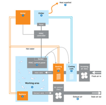
Heating, Ventilating and Air Conditioning is broad spectrum field, which covers wide areas from the simplest hand-stoked stove to exceptionally complicated air conditioning found in submarines and space shuttles. The size also varies respectively from refrigeration machines to bigger sizes which are used in industrial process. Further the designer considers the issues to keep the temperature comfortable according to the delicacy of the requirements. A Heating, Ventilating, and Air-Conditioning (HVAC) systems mainly controls the mechanical equipment’s like boiler, chiller, fans etc. HVAC mainly maintains the environment in a cost-effective manner. Where the environment lies on the basic factors for example pressure, ventilation, temperature, humidity [4] (Figure 2).
Figure 1:Motor Control Centre.
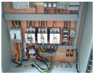
Figure 2:Functional Diagram of HVAC systems (Carbon Trust,2011).
Thermostat Sensor
A thermostat sensor is a device that regulates the flow of refrigerant from an air conditioning system, or the heating fluid from a mechanical heating system, by sensing the difference in temperature and switching the system on and off accordingly. It is usually a component of control systems that are used to maintain HVAC systems at a certain temperature called the cooling or heating set-point.
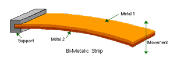
A typical thermostat used to control heating and cooling systems is made up of two layers of different metals, and the differential expansion of these metals will allow the sensor to detect a change in the temperature, which will activate a switch. This type of thermostat is known as a bi-metal thermostat, and can be made of metals like nickel, copper, aluminum, etc. to form a twolayered strip, which bends or curves, as shown in figure 1.3 below, upon expansion at different rates [5] (Figure 3).
Figure 3:Bi-metallic thermostat (CAPGO, 2013).
Methodologies, Design and Experimentation
Methodology
The link which is to be developed is between Motor control center and Heat ventilation air condition system with the help of sensor and the main challenge would be the automatic control of it. All electric motors typically require a control of some kind in order to operate. The controller on/off the motors and this mange’s speed and torque of the connected motors. The controller enables one more motor from central location called motor control center. The project is undertaken by the design of motor control centre on AutoCAD with the specification of the assembly components and the views are generated for the assembly design and fabrication which will be in prototype form. Developing the link between the motor control center and sensor to control the HVAC would be the next part [6].
Figure 4:Front view of the enclosure (AutoCAD).
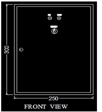
Figure 5:Inside view of the enclosure (AutoCAD).

Figure 6:Cable entry room block (AutoCAD).

Figure 7:End view of the enclosure (AutoCAD).
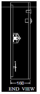
The design is of the motor control center is divided in two parts for the fabrication of the prototype the line diagram and the enclosure diagram is drawn in AutoCAD with specification according to the distribution board design, For the design and fabrication of the hardware the assembly of components are collected and assembled on distribution board according to the link developed for the control of HVAC systems (Figures 4-12).
Figure 8:Single Line Drawing in AutoCAD.
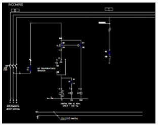
Figure 9:Indication lights and selector switch inserted in its positions.
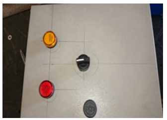
Figure 10:Assembling all components on Din Rail.
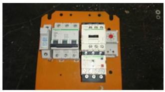
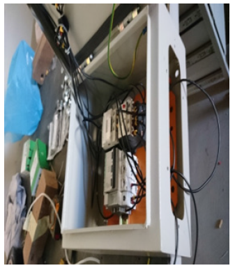
Figure 11:Wiring of the prototype according to line diagram.
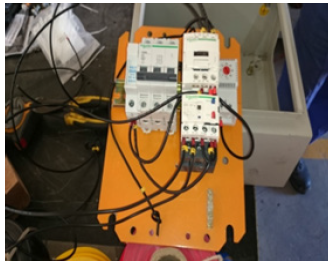
Figure 12:The prototype ready for testing.
Results and Analysis
Results
The next step after assembling the prototype is the testing phase. Where the wires are given to the main phase supply by accurately seeing the neutral and phase wires. Once properly wired to the supply the prototype showed the output desired with the increase in temperature from the thermostat the light switched off and when the temperature decreased the light switched on [7].
Outputs achieved
After checking the connection, the phase was given, and the prototype gave the output in auto mode and the prototype gave successful results. All the outputs here are taken in auto mode.
When switched to manual override mode to trip manually in case of error in sensor the outputs at first were not achieved due to short wiring connections but through testing again, the overload had a problem which was changed to get the desired output in manual mode [8] (Figures 13-16).
Figure 13:When temperature of thermostat goes above the value of desired temperature the supply is on and the HVAC system is running, and the indication light is on.
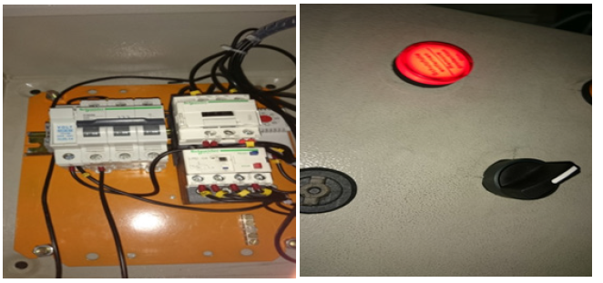
Figure 14:When temperature of thermostat below the value of desired temperature the supply is on and the HVAC system is off where indication light is off.
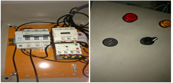
Figure 15:On hand/ manual mode, The system is working.
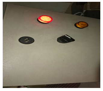
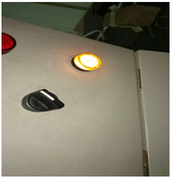
Figure 16:The green indication light turns on when the sensor doesn’t work, and the temperature is decreased it can be switched off by hand.
Conclusion
To conclude the project is designed and fabricated for controlling the HVAC systems automatically with the help of sensors. The link was successfully developed between the sensor and the motor control center and the temperature was regulated. The auto mode of the enclosure gives a perfect sensing of temperature as well as the override manual switch which can be applied when there is some error in sensor. It was a very informative project as an engineer and a challenge because of the new learning techniques and the link which had to be developed through the sensor and the direct exposure to industry to collect the components and learn the innovative skills related as an engineer. The important application of motor control center in the industry was learnt in depth and HVAC systems control was another big challenge to hurdle upon. One of the most important challenges which were faced was the controlling of the HVAC automatically as well as manually and develop the link of the same. The parts were rented from the industry for the design as the parts were really expensive to actually make a control of the HVAC with that small prototype. The prototype was kept as simple as possible as the higher connection and more parts create more complexity and the circuit is intricate
Acknowledgement
I would like to express my sincere profound gratefulness to Mr Sajjad Ahmed Shah to provide his expertise which aided in each step of the project .Furthermore would express my gratitude to each staff members Mk Switch Gear Division in helping at each and every step for completion of the project. In addition, I would like to thank my whole family for their wise counsel and sympathetic ear.
Conflict of Interest
No conflict of interest.
References
- Amarnath A, Blatt M (2008) Variable Refrigerant Flow: An Emerging Air Conditioner and Heat PumpTechnology.
- Australian Government Department of Industry (2014) n.d. Technology Background - Heating, Ventilation and Air Conditioning.
- Bucknell University (2014) n.d. Temperature Sensor - The Thermistor.
- Chimack MJ, Sellers D (2000) Using Extended Surface Air Filters in Heating Ventilation and Air Conditioning Systems: Reducing Utility and Maintenance Costs while Benefiting the Environment.
- Electronics Tutorials (2014) Temperature Sensors.
- (2014) Motor Control Centers.
- Schneider Electric SA (2008) Unlocking Energy Efficiency - Management and Control is the key.
- Sajjad SM (2021) Mustafa & Kamal Ashraf.
-
Syed Adeel Ahmed Shah. HVAC Automatically Controlled by Motor Control Center. Glob J Eng Sci. 9(5): 2022. GJES. MS.ID.000723.
-
HVAC, Motor control center, Direct online motor, Star delta motor, Sensor, Motor control
-

This work is licensed under a Creative Commons Attribution-NonCommercial 4.0 International License.


