 Research Article
Fuzzy Adaptive Control by Reference Model of a Submerged Electric Pump: Application to Photovoltaic Water Pumping
Ernest Kiata1,2,3*, Ndjiya Ngasop2,3,4, Nkenmoe Simo Justin1,2, Haman-Djalo1,2,4
1Faculty of Information and Communication Technologies, Protestant University of Central Africa /Yaounde/Cameroon.
2Laboratory of Information and Communication Technologies, Protestant University of Central Africa, /Yaounde/ Cameroon
3University of Ngaoundere/ Cameroon, Department of physics, Faculty of Science, Cameroon
4Department of the Electric, Energy and Engineering Automatic, national school of agro-industrial Sciences (ENSAI), University of Ngaoundere, Cameroon
Ernest Kiata, Faculty of Information and Communication Technologies, Protestant University of Central Africa /Yaounde/Cameroon.
Received Date: November 25, 2022; Published Date: January 10, 2023
Abstract
In developing countries, remote areas and particularly in Africa, water pumping is increasingly used to gain access to water. Submerged electric pumps face two major operating problems: variations in internal parameters and external disturbances. This article proposes an optimal control strategy for a photovoltaic pumping system, based on the dual use of fuzzy logic to allow access to water in quantity. The complete system, operating over the sun is modelled and simulated on Matlab/Simulink including a photovoltaic generator, an adaptation stage (chopper-inverter) and a submerged electric pump. The switch (IGBT) of the booster chopper is controlled by a fuzzy controller that regularly adjusts the duty cycle according to the climatic conditions and ensures the operation of the submerged electric pump at the maximum power point. Adaptive control by reference model of the electropump’s speed based on fuzzy logic is used and presents a better efficiency.
Keywords:Adaptive control; Submersible pump; Fuzzy logic; MPPT; Photovoltaic energy
Introduction
The United Nations in its latest report on the development of water resources estimates that 30% of the world’s population still does not have access to safe drinking water at home [1]. According to the World Health Organization, 884 million people worldwide do not have a basic service of access to drinking water. Of the 884 million people who do not have access to safe drinking water, 263 million have to travel thirty minutes round trip to the nearest water point. 423 million people drink well or spring water that is not protected from contamination. As many as 159 million people collect their drinking water in a river, lake or irrigation canal, at the risk of contamination by chemicals and feces [2].
In Cameroon, out of nearly 24 million inhabitants, about 8 million 890,000 do not have access to a drinking water service. Only 52.3% of the population at the national level uses an improved (modern) sanitation facility. Faced with these alarming figures, regular handwashing to protect against COVID-19 and other infectious diseases is not possible in the absence of water.
One of the most effective solutions that would ensure access to water in quantity, regardless of the location, is the use of photovoltaic conversion of solar energy to operate water pumps. Solar-run photovoltaic pumping systems typically consist of a photovoltaic generator (GPV), energy converters, and an electric pump.
The main disadvantage to the use of such a system continues to be their high initial cost and low water yield. The investigations carried out to optimize the operation of this system in recent years are grouped into two categories. The first concerns those who seek to optimize the operation of the GPV through the search for the maximum power point (MPPT) via different algorithms and static converters [3-6]. The second category groups those who seek to optimize the electropump’s control [7-9].
This work fits into both categories of research, through the coupled use of two fuzzy regulators. The first regulator allows the photovoltaic generator to provide the maximum power to the submerged electric pump and the second regulator, through an adaptive control by reference model allows to optimize the rotation of the speed submerged electric pump’s motor regardless of external disturbances.
This article in its joints, first presents the title Material and Methods which illustrate in detail the Simulink model of the GPV, the adaptation stage (chopper and inverter) integrating the technique of locking the duty cycle through the MPPT-FL control and then the submerged electric pump’s Simulink model. Then a presentation discussed the results obtained and we finish with a conclusion.
Equipment and Methods
Equipment
As part of this work, we used an acer computer Intel (R) dual core processor, 2.3 GHz, Matlab R2018a software, a Helios H750 brand photovoltaic module to power the submerged electric pump and an experimental database of climate parameters recorded on January 11, 2021 (from 9am to 4pm) at the University of Ngaoundere in Cameroon.
Methods
Photovoltaic generator:We use in this article the basic structure of a one-diode photovoltaic cell. The equivalent circuit of the GPV and the different equations leading to equation (1) are provided in [10].

The block diagram in Figure 1 shows the Simulink model of the PV module (a) and the GPV (b), based on equation (1) whose parameters are solved by the Newton-Raphson method in the Matfile.
Figure 1:Simulink model of the module and PV generator.
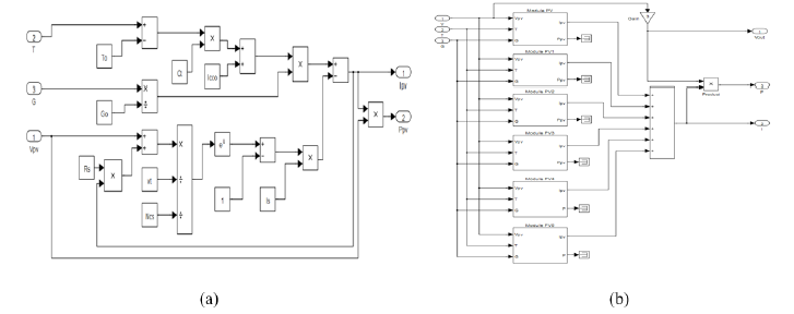
For the simulation of the GPV, we associate in series 3 rows of 6 PV modules in parallel (NP = 6. Ns = 3) as shown in (Figure 1b), for an available power of 1559.09 W under 24.06 A and 64.8 V and allowing the pump to supply 1.3 l / s under 6 bars.
Adaptation stage of the photovoltaic generator:
a. DC-DC Converter: Boost chopper:The main role of the Simulink model of the booster chopper shown in (Figure 2), is to change the voltage from a low value to a higher value by varying the cyclic ratio (d) in the following relationships (2) and (3).


Vin et lin represent respectively the voltage and current at the input of the chopper and Vout, Iout represent the output.
The values of the inductance L and the capacity C of the converter are calculated as follows:

With f as frequency and ΔI ,ΔV the ripple size of the current and voltage respectively. Using the maximum values of current and voltage, the numerical application of relationships (3) and (4) give 30 μH and 470 μF respectively.
At the input of the control signal, a comparator makes it possible to make the analysis between a triangular signal of frequency 100 kHz and the cyclic ratio provided by the MPPT-fuzzy control algorithm.
b. Implementation of the MPPT-blur control algorithm: MPPT allows the GPV to operate at maximum power despite variations in sunlight, temperature and load [9,12,13]. We find in the literature about twenty methods based on the research of the PPM PV modules. Control by fuzzy logic offers the advantage of being robust, efficient and works at PPM without oscillation [3,5]. There are different ways to implement a fuzzy regulator but in general the presentation adopted is divided into three stages: fuzzification, inference and defuzzification (Figure 3).
Figure 2:Simulink model of the module and PV generator.
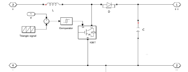
Figure 3:Simulink model of the module and PV generator.

The fuzzification step allows the conversion of input variables into fuzzy variables. In our case, we have two entries: the error (err) and the variation of the error (derr) defined by the following relationships (6) and (7).

Where Ppv(k) and Vpv(k) are respectively the power and instantaneous voltage of the GPV. These quantities are assigned language variables: LN (Large Negative), SN (Small Negative), ZE (Zero), SP (Small Positive) and LP (Large Positive). The different inference rules that govern the operation of the regulator are given in (Table 1) and the membership functions of the inputs and outputs used are given in [10].
We take as an example of the control rules of Table 1: “If err is LP and derr is ZE Then d is LN”. This means that: “If the operating point is far from the point of maximum power (PPM) to the left side and the change in the slope of the X curve is about Zero; So, decrease the cyclical ratio (d) widely”. Finally, in defuzzification, we convert the fuzzy output subsets into a numerical value by the centre gravity method and multiply it by the scale factor to have the normalized control signal. We present in (Figure 4) below the implementation of our fuzzy regulator.
Figure 4:Simulink model of the fuzzy regulator.

Table 1:Inference Rules.

c. DC-AC Converter: Single-Phase inverter:The single-phase inverter illustrated by its Simulink model (Figure 5) allows the manufacture of alternating voltage from the DC voltage on the chopper. The pulse width modulation (PWM) technique is used to control the switching bridge of the inverter.
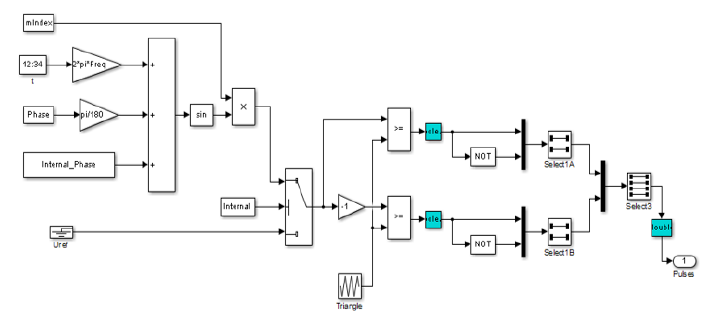
The pulses (G1, G2, G3 and G4) of the switches (IGBT) of the same arm are complementary and generated by the MLI control implemented in the following (Figure 6).
Figure 5:Simulink model of the fuzzy regulator.
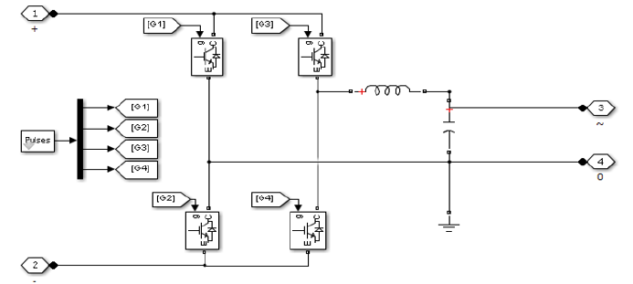
Figure 6:PWM Implementation.
d. Implementing adaptive control by reference model: The submersible pump is the most important module of the photovoltaic pumping system. Several parameters and factors prevent its optimal operation. These parameters are meteorological, electrical, mechanical and hydraulic. Adaptive control of the rotational speed of the pump motor is the best method to optimise its operation. We have developed a method to regulate the speed of rotation of the pump motor regardless of the parameters and factors that influence it. We present in (Figure 7) below, the “Simulink” model of the fuzzy control loop of the rotational speed of the submerged pump motor.
As shown in (Figure 7), the entries of the fuzzy regulator are calculated at time k from the following equations 8 and 9.
Figure 7:“Simulink” model of the fuzzy pump speed control.
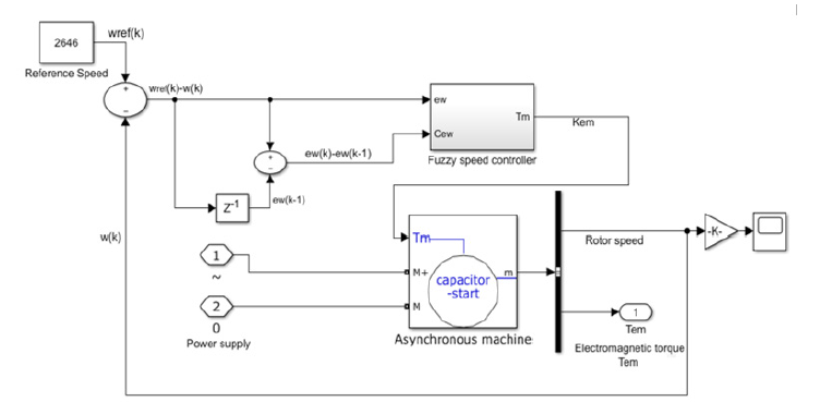
Figure 8:Membership functions of: (a) the ew entry; (b) the Cew input and (c) the Tm output of the fuzzy cruise control.
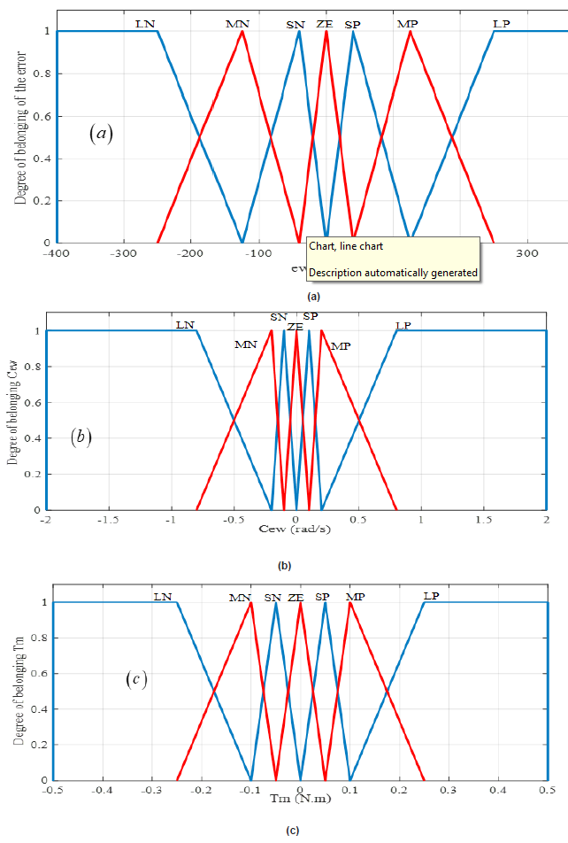
Figure 9:Simulink model of the single-phase motor coupled to the centrifugal pump.
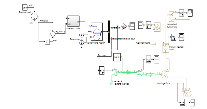
Table 2:Fuzzification of the assemblies for cruise control.


The control signal provided by the fuzzy regulator corresponds to the mechanical torque ( ) m T k of the pump motor, obtained by the centre of gravity method as shown in relation 10.

After several simulation tests we established the following ranges of input and output quantities: Speed error ew(k) :[-400 ;400] rad/s; Speed error change Cew (k) :[-2 ;2] rad/s; Mechanical torque change Tm(k) :[-0,5 ;0,5] N.m.
e. To distribute this data in the blurred spaces, we first defined the fuzzy sets. In general, we introduce for a variable x, three, five or seven sets. A finer subdivision, i.e., more than seven sets, generally does not improve the dynamic behaviour of the control by fuzzy logic. On the other hand, such a choice would complicate the formulation of the regulator setting by fuzzy logic. After several experiments and simulations, we find that, to increase the robustness of the fuzzy regulator towards the engine parameters, it is advantageous to choose a greater density around the zero value of a quantity. (Figure 8) shows the fuzzy distribution diagram for the input quantities of the cruise control used in this part. The triangular shape is used for membership functions except for the ends of each membership function where the trapezoidal shape is used. The fuzzy distribution is symmetrical, not equidistant. The meaning of the symbols and the ranges of value designated to the fuzzy sets are shown in (Table 2). Simulink model of the submerged electric pump: We show in (Figure 9) below the Simulink
Results and Discussion
Influences of irradiance and temperature variation on GPV
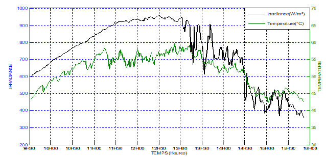
(Figure 10) shows the behaviour of irradiance and temperature during a day (from 9 am to 4 pm) at the University of Ngaoundere Cameroon. We find that the irradiance reaches its maximum value at about 12 hours and then begins to fall. These curves allow us to conclude that meteorological parameters in Adamawa fluctuate constantly.
Figure 10:Irradiance and temperature curves during a day.
Impact of the MPPT-Fuzzy controller on the voltage from the GPV
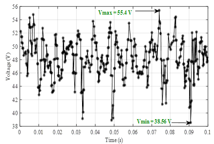
Having the certainty that the GPV is working normally, it is thus possible to power the complete system. The fluctuation of the voltage at the terminals of the GPV between 38.21 V and 55.4 V as shown in Figure 11 allows us to conclude at first that powering an electric pump over the sun and expecting a regular flow of water is almost impossible. But thanks to the MPPT-blur control performed at the chopper input, the voltage was boosted and made almost stable at the average value of 222.3 V (Figure 12). Figure 12 through these two curves makes a comparison of the voltages at the output of the booster chopper under the “MPPT-P&O” command and under the “MPPT-blur” command. The analysis of these curves shows that the “MPPT-blur” control optimises and stabilises the voltage from the GPV better than the “MPPT-P&O specific” command.
Figure 11:Voltage at GPV output.
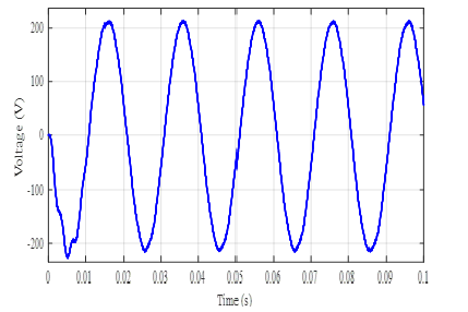
The DC voltage from the chopper is applied to the input of the inverter, we obtain at the output an alternating voltage of amplitude 223.7 V with a modulation index of 0.98 and a period of 0.02 s (Figure 13). In order to obtain a frequency of 50 Hz according to the nominal frequency of the electric pump, a low pass filter is placed at the output of the inverter as modelled in (Figure 5).
Figure 12:Tension at the outlet of the chopper.
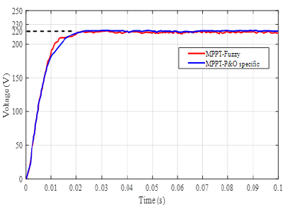
Figure 13:Voltage at the outlet of the inverter.
(Figure 14) shows the speed of rotation of the motor driving the centrifugal pump. We notice that when the weather conditions are favourable, the engine quickly reaches its permanent speed (2820 rpm). This result is consistent with that found in [10,11] with the only difference that the P&O controller replaced by Mandani’s fuzzy controller improves the response time of the motor.
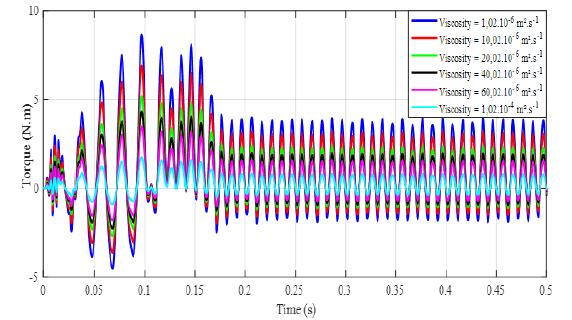
At the same time, we studied the influence of the viscosity of the pumped fluid on the speed and electromagnetic torque of the electropump. From the analysis of the curves in (Figures 14 and 15), we see that the rotational speed and torque of the motor decreases when the viscosity of the fluid to be pumped becomes greater and greater. Thus, a highly viscous fluid can prevent the pump from turning thus reducing its efficiency to zero.
Impact of Fuzzy Adaptive Control by Reference Model on Electro pump Speed
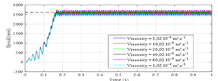
(Figure 16) shows the different behaviours of the rotational speed of the electropump under several values of the viscosity of the pumped fluid using the fuzzy adaptive control by reference model.
By varying the viscosity of the pumped fluid, we find that the rotational speed of the submerged pump motor does not deviate much from the average reference speed (2646 rpm) that must be followed by the fuzzy cruise control. We present in (Table 3), the rotational speeds of the submerged electropump before and after regulation, for different viscosity values.
Table 3:Motor rotation speed.

Figure 14:Voltage at the outlet of the inverter.
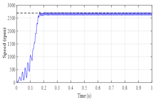
Figure 15:Influence of viscosity on velocity.
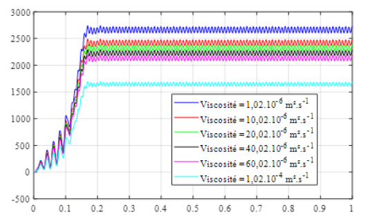
Figure 16:Influence of viscosity on engine torque.
When the submerged electric pump operates without a control loop for different values of the viscosity of the pumped fluid, the average speed of the electropump is 2230 rpm, a difference of 416 rpm from the reference speed. By using the fuzzy regulator, the electropump keeps an average speed of 2570 rpm or a difference of 76 rpm. We therefore come to the conclusion that the use of adaptive blur control by reference model makes it possible to optimize by 340 rpm the average speed of rotation of the submerged electropump regardless of the viscosity of the pumped fluid (Figure 17).
Figure 17:Behaviour of the rotational speed after adaptation regulation.
Conclusion
In this work, it was a question of proposing a strategy for optimizing the operation of photovoltaic pumping systems in the face of variations in meteorological parameters and the viscosity of the pumped fluid. The use of the fuzzy MPPT algorithm for the control of the chopper control pulses, allows the optimal conversion of irradiance. Adaptive reference model control with a status observer, forces the controlled electric pump to follow the desired reference speed, using a control law based on fuzzy logic, for realtime automatic adjustment of the pump’s rotational speed. The simulation results obtained are appreciable in terms of robustness, with regard to the presence of disturbances.
Acknowledgement
None.
Conflict of Interest
No Conflict of interest.
References
- UN-Water (2022) World Water Day. United Nations.
- WHO (2021) Access to Water in the World. Observatory of Inequalities.
- H Abbes, H Abid, K Loukil, A Toumi, M Abid, et al. (2014) Comparative study of five MPPT control algorithms for a photovoltaic system. Revue des Energies Renouvelables 17(3) : 435-445.
- A Meflah, T Alloui (2012) Control of a photovoltaic pumping chain over the sun. Renewable Energy Review 15(3): 489-499.
- M Ajaamoum, M Kourchi, B Bouachrine, A Ihlal, L Bouhouch, et al. (2015) Comparison of Takagi-Sugeno fuzzy controller and the command "P & O" for extracting the maximum power from a photovoltaic system. International Journal of Innovation and Applied Studies 10(1): 192-206.
- A Hadjaissa, SM Ait Cheikh, K Ameur, N Esounbouli (2016) A GA based optimization of a fuzzy-based MPPT controler of a photovoltaic pumping system, Case study for Laghouat, Algeria. ScienceDirect 49(12): 692-697.
- H Bouzeria, C Fetha, T Bahi, I Abadlia, Z Layate, et al. (2015) Fuzzy Logic Space Vector Direct Torque Control of PMSM for Photovoltaic Water Pumping System. ScienceDirect 74(1) : 760-771.
- Bouldjedri, CE Feraga, Abdallah (2016) Performance of a Photovoltaic Pumping System Driven by a Single Phase Induction Motor Connected to a Photovoltaic Generator. Automatika 57(1): 163-172.
- Y Bakelli, A Hadj Ara, B Azoui (2012) Modelling of a motor-pump unit in the photovoltaic pumping test bench of the URAER Ghardaïa. Renewable Energy Review 15(1):103-109.
- Ernest Kiata, Ndjiya Ngasop, Haman-Djalo, Kayem Joseph (2017) Optimization of the operation of a pump system and photovoltaic membrane ultrafiltration by use of a fuzzy controller. Global Journal of Engineering Science and Research 4(12): 76-86.
- A Boussaib, M Kamta, J Kayem, D Toader, S. Haragus, et al. (2015) Characterization of photovoltaic pumping system model without battery storage by Matlab/Simulink. IEEE 8(11): 37-41.
- FZ Zerhouni, MH Zerhouni, M Zegrar, AB Stambouli (2012) Search for the maximum power of a photovoltaic generator. ACTA ELECTROTEHNICA 53(2) : 130-133.
- N Aouchiche, MS A Cheikh, A Malek (2013) Pursuit of the maximum power point of a photovoltaic system by conductance incrementation and disturbance & observation methods. Renewable Energy Review 16(3): 485- 498.
-
Ernest Kiata*, Ndjiya Ngasop, Nkenmoe Simo Justin and Haman-Djalo. Fuzzy Adaptive Control by Reference Model of a Submerged Electric Pump: Application to Photovoltaic Water Pumping. Glob J Eng Sci. 10(5): 2023. GJES.MS.ID.000746.
-
Adaptive control, Submersible pump, Fuzzy logic, MPPT, Photovoltaic energy
-

This work is licensed under a Creative Commons Attribution-NonCommercial 4.0 International License.


