 Research Article
Adaptive Signal Control under Platooned Connected Vehicles Environment: Phase Allocation Optimization Using Platoons Departure and Advisory Speed Trajectory Method
Ahmed Alzahrani1*, Mohammad D Alahmadi2, Adel Abu Hashim3 and Ren Moses4
1Graduate Research Assistant, Department of Civil and Environmental Engineering, FAMU-FSU College of Engineering, 2525 Pottsdamer St, Tallahassee, FL 32310, USA
2Assistant professor, Department of Software Engineering, College of Computer Science and Engineering, University of Jeddah, Jeddah, Saudi Arabia
3Computer and Systems Engineer, Egyptian General Survey Authority, Al Mohafaza St, As Sayadin, Zagazig 2, Ash Sharqia Governorate 44516, Egypt
4Professor, Department of Civil and Environmental Engineering, FAMU-FSU College of Engineering, 2525 Pottsdamer St, Tallahassee, FL 32310, USA
Ahmed Alzahrani, Graduate Research Assistant, Department of Civil and Environmental Engineering, FAMU-FSU College of Engineering, 2525 Pottsdamer St, Tallahassee, FL 32310, USA..
Received Date:February 07, 2023; Published Date:February 20, 2023
Abstract
The current traffic control signals primarily rely on vehicle detectors as the primary input source for the controller logic. Sensors are based on infrastructures and cannot determine the direction and speed of vehicles directly. The advancements in wireless communication technology are expected to significantly enhance vehicle-to-vehicle (V2V) and vehicle-to-infrastructure (V2I) communications. In real-time traffic signal planning, many researchers have applied different methods to improve traffic performance (e.g., minimize queue length). Many researchers have studied the optimization of traffic signals in an effort to improve traffic flow and reduce congestion. However, despite their efforts, the results of these studies have not been significant when applied to high-demand traffic scenarios. A real-time adaptive signal algorithm based on platooned CVs was developed to produce an optimized signal plan. The developed algorithm’s main performance measures are minimizing the average vehicle delay by utilizing the CVs data and decreasing the average number of stops by providing platoon advisory speed. The developed algorithm outperformed traditional signal plans and individual CV-based algorithms in performance measures for various travel demands.
Keywords:Connected vehicles; Platoon-based algorithm; Individual vehicle-based algorithm; Departure sequence; Trajectory speed advisory
Abbreviations:The following abbreviations are used in this manuscript: CVs - Connected vehicles; V2V - Vehicle to vehicle; V2I - Vehicle to infrastructure; DSCR - Dedicated short-range communication; IDM - Intelligent driving model; VISSIM - Verkehr In Stadten – SIMulations model; DLL - Dynamic library link; EDM - External driving module; FDOT - Florida department of transportation; HCM - Highway Capacity Manual
Introduction
The number of car owners in urban areas has increased rapidly in recent years. As a result, road congestion, gas emissions, fuel consumption, and vehicle miles travelled have increased [1]. 5 to 10 % of all the traffic delay is estimated from the signal delay alone, and in other words, around 295 million of vehicle-hours delay on significant roadways are caused by traffic signals [2]. Furthermore, the current design and management of roads and other transportation infrastructure in urban areas are inadequate to handle the increasing volume of traffic [3]. According to the Network Operating Plans, traffic signal control systems are crucial in improving traffic flow. They are the primary way to implement smart road concepts within the road network [4]. Optimizing traffic signal control in correspondence with road demand is essential to increase efficiency and improve traffic conditions. Fixed-time, actuated, and adaptive are three stages of traditional signal control strategies that have been used. Fixed time signal determines the signal timing based on historical traffic data. However, as traffic conditions and demands vary over time, using fixed timing parameters for traffic control cannot effectively adapt to such changes [5]. For isolated intersections, actuated signal controllers are usually adapted. Loop detectors, video detectors, infrared sensors, or radar are sensors built into the infrastructure that can be utilized to collect information about traffic demand patterns. This data is then used to adjust the traffic signal cycle length, time allocated to each phase, and even phase order [6]. This kind of signal controller mainly utilizes predetermined static parameters, such as the minimum and maximum duration of the green time [7].
Furthermore, by utilizing data from upstream detectors to anticipate incoming traffic flow, the adaptive traffic signal control strategy is used for an arterial or road network to implement the optimal timing strategy. SCAT, OPAC, SCOOT, and RHODES are examples of adaptive traffic control systems currently used worldwide for traffic signals. These traditional traffic signals are designed on a macroscopic level of traffic and do not consider individual vehicle information. Therefore, these traditional signals cannot maintain dynamic real-traffic patterns [8]. Connected vehicles (CVs) and advanced mobile computing technology have the potential to provide more efficient traffic signal algorithms. Collecting and sharing detailed traffic pattern data is possible with vehicle-to-vehicle communications (V2V). In addition, CVs can impact the means of traffic signals through their vehicle to infrastructure communications (V2I) [9].
Problem Statement
One of the traditional adaptive traffic signal control’s main objectives is to minimize average vehicle delays and decrease the number of stops at intersections [10]. However, according to [11], actuated and adaptive signal control strategies have two main limitations. The first limitation is that these detectors provide information only instantaneously to the vehicle when the vehicle crosses the sensor and cannot measure the status data of the vehicle, such as speed, position, acceleration, etc. The second limitation is in case of the complete lack of one or more loop detectors; adaptive signal control system performance may be considerably devalued. In addition, fixed sensors are considered to have high installation and maintenance costs.
In 2004, Miller and Huang put forth the idea of engaging wireless communication in the design of a smart intersection [12]. The main objective of that study is to create an example application of a simple and reliable protocol that has been presented for electronic traffic signals. Even though their system was not meant to be tested at an intersection, the research provides the basis for exploring the wireless technology field for adaptive traffic control systems. Connected vehicles (CVs), which is a developing technology, use short-range communications (DSRC) to enable communication between vehicles and with infrastructure [13]. The field of connected vehicles requires the development and integration of various new technologies, such as; advanced wireless communication systems, powerful computer processing capabilities within the vehicle, sophisticated sensors, GPS navigation systems, and smart infrastructure to establish a connected network environment [1]. Unlike traditional sensors, real-time information, such as location, speed, acceleration, etc., can be collected with the help of CV technology. These data can be used to evaluate the traffic condition on roadway networks to draw a complete picture of the intersection nearby vehicles’ status [14]. Therefore, an improved design of the signal plane can be developed to improve traffic flow. Various optimization methods have been utilized in this promising field’s studies.
The remainder of this work consists of the following sections: First, related work of the traditional and the connected signal plans studies is summarized in the next section. The algorithm used in this research is extensively illustrated in the fourth section. The simulation model and scenarios are discussed in the fifth section. The results discussed and compared to other studies are presented in the sixth section. Finally, the last two sections propose a discussion with some concluding remarks and future work.
Related Work
Many studies have illustrated the traditional traffic signal control algorithms in detail. [15] investigated the control philosophies used by numerous different traffic signal algorithms. These algorithms were categorized according to the kind of data utilized as input for signal control (2015). In addition, [16] reviewed the CAV coordination research.
Furthermore, taking advantage of the connected environment, several studies have proposed algorithms to optimize signal timing and phasing planes using individual vehicle information, such as; speed, acceleration, location, etc. These studies have considered various objectives, for instance, vehicle or person delay [9,17], summation of travel time [18], total queue length [19], and or merging different objectives as in [20]. By considering previous objectives, various strategies have been developed within CV-based adaptive traffic control systems to optimize the duration of the signal cycle [9], green split [21], and signal phase allocation [19]. Most of these studies have arrived at the same conclusion: CV-based algorithms outperform traditional signal control algorithms.
Some other studies tried to optimize the vehicle departure sequence using the CV information. Different performance measures were evaluated, such as; travel time [22], average vehicle delay within a segment [23], average queue lengths [24], and minimization of evacuation time [25]. It is important to note that recent studies have primarily assumed that all or most vehicles have a wireless connection. However, it is unlikely that this technology will be widely used by vehicles for another 30 years [26]. Only a few studies have considered the possibility of incomplete vehicle status information or vehicles without wireless connections. In contrast, only two studies have attempted to estimate the arrival information for these traditional vehicles and incorporated them into their departure sequence algorithm [27,28].
With the advent of technology that allows a vehicle’s trajectory to be adjusted in real-time through changes in speed and acceleration, research on connected vehicles has increased in recent years. A “reservation-based strategy” is a method of longitudinal trajectory design. It considers evaluating requests from drivers who want to reserve a specific time block at an intersection and deciding whether to approve or reject these requests in real-time. Many studies have adopted this methodology, where some researchers have focused on only CVs penetration [29], while others have looked at both CVs and non-CVs [30]. Despite the potential benefits of reducing vehicle delays, this methodology is incompatible with existing traffic signal controllers and raises significant safety concerns [27,31,32]. Most studies assume that all vehicles are equipped with CV technology, but only a few consider lower penetration rates. The studies being referred to either lack proper safety considerations [29,33] or do not consider the acceleration and deceleration of vehicles [27], making them insufficient and requiring additional computational resources.
One of the latest studies published recently proposed a real- time information optimization algorithm. This paper has suggested using the information from CVs and AVs near the signalized intersection to minimize the Average vehicle delay by optimizing the individual vehicle departure sequence and offering longitudinal speed guidance for CVs or AVs to decrease the number of stops per vehicle [26]. That study investigated its algorithm only for an isolated intersection with two single-lane approaches without left turn movements, which a simple signal of two phases should control it. It was impossible to create a more realistic intersection, such as one with multiple lanes and conflicting left turn movements, as well as more options for vehicles and phasing, due to the significant amount of time needed for computation. Additionally, the limited scope of considering only one mode of transportation limits its practical use in real-world situations.
Vehicle platooning is expected to be one of the travel modes in the near future [34]. In addition, vehicle platooning can improve traffic efficiency in multiple subjects [33]. Recently, many researchers have considered CVs platooning to develop adaptive traffic signal controls to improve traffic movements near intersections. However, most of the platoon-based adaptive traffic signal reviewed studies under CVs environments did not include different penetration rates of traditional vehicles [35]. It is not anticipated that all vehicles will transition to connected vehicles within a brief timeframe. In addition, some proposed algorithms propose driving models that assume a sudden change in CVs speed.
Despite the potential benefits of platooned connected vehicles, many studies have shown that the impact of this technology on traffic flow and signal timing is insignificant under high demand conditions. For example, [36] a study by Wang et al. found that while platooning can reduce congestion and improve traffic flow, the results were insignificant under high demand conditions. Another study by Chen et al. focused on the communication between vehicles and the infrastructure and found that real-time communication is crucial for the success of platooning systems. Still, the impact on traffic flow was insignificant under high demand conditions [37]. Several other studies [38-40] have investigated the optimal signal timing for platooned CVs. These studies have also shown that the impact of platooned CVs on traffic flow and signal timing is insignificant under high demand conditions.
To address the limitations of prior methods, the new algorithm is designed to focus on the movement of platoons instead of individual vehicles, significantly simplifying the computational process while maintaining high-performance levels. The main benefit of using the platoon-based algorithm is that it reduces the complexity of the computational demands and enables the algorithm to be applied to more realistic situations, which the individual vehicle- based algorithm cannot handle. While vehicle-based algorithms give the trajectory speed guidance for each vehicle, the developed algorithm proposes an advisory speed trajectory for the lead vehicle for each platoon, which further reduces the computational time. Additionally, the algorithm that has been created accounts for more accurate vehicle dynamics, such as acceleration and deceleration patterns, by utilizing a modified version of the Intelligent Driving Model (IDM). Furthermore, compared to existing approaches, the developed algorithm demonstrates a significant improvement in optimizing traffic signals under high traffic demands, providing a more efficient and reliable solution for managing urban traffic flow.
Developed Algorithm
In this section, a platoon-based signal control algorithm is illustrated. The goal of this algorithm is to provide both levels of signal optimization control, which include departure sequence and trajectory speed guidance. The proposed algorithm was developed based on platoons’ departure using a simple two-approach signalized intersection (Figure 1). A platoon departure algorithm has several unique advantages over the individual vehicle algorithm. Firstly, the developed algorithm uses CV information to identify platoons of arriving or stopped vehicles and optimizes the signal timing plan based on the location, speed, and number of vehicles in each platoon. Thereby reducing the computational demands required and allowing for application to more realistic intersections with higher and more complex vehicle flows. Secondly, an efficient trajectory speed guidance was developed to minimize the number of stops at the intersection while also accommodating the upstream traffic. Thirdly, the developed algorithm only gives an advisory speed to the lead CV in each platoon, which controls the whole platoon. Lastly, using a modified Intelligent Driving Model (IDM), the algorithm considers a more realistic model of vehicle dynamics near the intersection by accounting for gradual acceleration and deceleration in the advisory speed guidance.
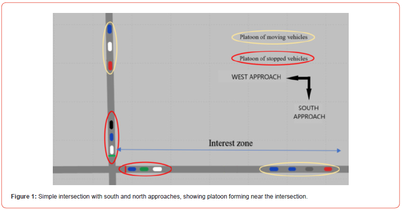
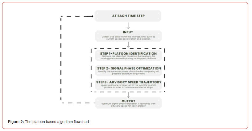
taken into consideration and referred to as the west (W) and the south (S) approaches (Figure 1). The following Figure 2 illustrates the logic of the proposed platoon-based algorithm. The control algorithm forms a discrete loop that repeats itself each time step. The input depends on the collected data, such as; speed, acceleration, location, etc., of CVs within the interest zone. The first step would be identifying platoons (stopped or moving) and estimating unequipped vehicles near the intersection. The next step would be to select the most suitable signal phase based on factors such as location, speed, number of platoons, and number of vehicles within the interest zone, to minimize the average delay for vehicles. The third step’s main objective is to find the advisory speed of each departure sequence that would lead to the minimum number of stops using IDM. Steps two and three work in parallel, where advisory speed is generated to ensure the optimum signal phase allocation is met in every possible departure sequence.
cles (CVs) that can transmit location and speed to a central controller and receive direct control instructions. The two vehicle types were evaluated and compared. The input for the algorithm used is a set of estimated arrival times at the intersection stop line for all CVs within a designated area around the intersection (as shown in Figure 1). The list of vehicles and when they are expected to arrive is updated at every time step. Data from stopped connected vehicles (CVs) is used to recognize any traditional vehicles that are stopped downstream of a stopped CV. These traditional vehicles are found when the distance between a stopped CV and the intersection stop bar or the nearest downstream CV in the same lane is longer than the length of a vehicle, indicating the presence of a traditional vehicle. Traditional vehicles recognized in this way are then added to the list of vehicles the algorithm considers. Equation (1) and equation (2) can estimate the number of traditional vehicles between two CVs, or a CV and the stop line, respectively, where results are rounded to the nearest integer.

Where xc is the distance of the CV labeled as c to the downstream of the intersection, and xc′ is the distance of the proceeding CV labeled as c′ to the downstream of the intersection. While lc is the average spacing. The platoon-based algorithm steps are illustrated in the following subsections:
Platoon identification
Vehicle platoons at an intersection are detected using data from individual CVs. The main methods for detecting platoons involve evaluating headway (distance between moving vehicles) and spacing (the distance between two successive stopped vehicles with reference to the same point). Vehicles with a headway or spacing that falls below a predetermined threshold are considered part of a platoon. The spacing threshold is used to determine platoons of stopped vehicles at the intersection, while the headway threshold is used to determine moving platoons approaching the intersection. CVs and traditional vehicles are considered in the platooning process, but traditional vehicles are only determined by their spacing. A platoon can consist of only one vehicle, such as when a vehicle is travelling alone or when a CV is the only vehicle in a group of traditional vehicles.
Signal phase optimization
The main objective of this step is to determine the optimum platoon sequence departure, which results in the lowest average vehicle delay. Contrary to individual vehicle-based algorithms, where the departure sequence is estimated based on all vehicles in the interest zone, the platoon-based algorithm considers all vehicles in each platoon identified in the first step to be departed together. The platoon may be broken if the maximum green time is reached before all vehicles cross the intersection. In this case, the upcoming platoons may join the platoon that is in the queue. Implementing platoons limits the number of vehicle departure sequences that can be considered, as vehicles within the same platoon must be given priority to move through the intersection before vehicles from other platoons can pass. This condition makes the algorithm more stringent than algorithms that only consider individual vehicles.
It is expected that when a CV enters the interest zone, it will continuously provide updates on its location and speed. Thus, the platoons’ arrival time and desired speed are obtained to determine the optimum departure sequence. Equation (3) is the primary objective function, where the departure sequence with the minimum average vehicle delay was chosen as the optimum departure sequence.

The predicted time of platoon p departure from the intersection’s downstream end in sequence s, known as the vehicle delay, is the same as the expected departure time for the last vehicle in the platoon Dcs and can be calculated using equation (4). vp represents the virtual departure of platoon p from the intersection’s downstream end, assuming no interference or delays in traffic. It can be calculated using the position of the platoon’s last vehicle and the free-flow traffic speed. This equation’s main objective is to find the minimum delay the controller imposes on traffic for all the possible platoon departure sequences. It is assumed each vehicle in the intersection has a set of unique data set c, which includes (o, s, a). Where o ∈ O is the order of car c in the platoon; s ∈ S is the sequence of departure of platoon s, and vehicle c is located at a approach. Equation (4) was used to calculate Dcs based on its location in the platoon.

The delay penalty of a PC refers to the amount of time it takes for a vehicle to accelerate and go through the intersection and can be calculated as in equation (5), while Sm is the saturation headway for approach m.

The previous equation was driven with the basic kinematic law, assuming the initial speed equals zero since the vehicles are stopped at the queue. a is the maximum acceleration, and l is the distance to the intersection’s downstream end. Equations (3 through 5) were applied to find a stopped platoon’s delay to generate equation (6). In contrast, for moving platoons, the platoon’s first vehicle delay was multiplied by the total number of vehicles within the platoon, since a platoon should have similar headway between its vehicles.

Where n represents the count of the last vehicle in the stopped platoon and can be estimated by knowing the location of the last CVs with zero speed. Moreover, it should be noted that the maximum green time is used as a constraint, where no phase allocation should exceed the maximum green time.
Advisory speed trajectory
This step aims to minimize the number of stops and the amount of time spent driving by enabling some vehicles to speed up and pass through the intersection before the traffic light turns red while allowing other vehicles to pass without stopping. The algorithm enhances the performance of vehicles passing through the intersection by adapting the IDM to meet the driver’s needs at the intersection. The algorithm continually searches for the best vehicle order to depart based on equation (3) at each time step. An advisory speed is projected to each platoon’s lead CV based on three scenarios. Suppose the optimum departure sequence is found where the lead CV and its platoon should pass through the intersection during the active green time. In that case, the maximum speed strategy is adopted to ensure that most vehicles can pass before the subsequent departure of the cycle. If the optimum departure sequence is found where the lead CV and its platoon should pass through the next green time without stopping within the allowable range of speed, between the minimum and the maximum speed limit, then a desired speed would be calculated and adopted. Suppose the optimum departure sequence is found that the lead CV and its platoon cannot pass in scenario 1 or 2. In that case, the deceleration stop strategy is adopted, where the lead CV should drive at the minimum allowable speed.
A car-following model must be adopted to execute the strategies
mentioned above. According to [35], a car following model that
mimics driver behavior should have the following requirements:
• As speed increases, acceleration decreases.
• As the distance to the vehicle in front increases, the acceleration
increases.
• As the speed of the vehicle in front increases, the acceleration
also increases
• The distance between vehicles (bumper-to-bumper) is kept at
a minimum distance S0 from the vehicle in front, and no backward
movements are allowed.
IDM Car following model (equations 7 through 10) is a common car-following model introduced by Treiber and others [41], and it meets the previous requirement. Furthermore, IDM can maintain a suitable distance from the vehicle in front, maintaining a specific speed and ensuring that acceleration is comfortable.
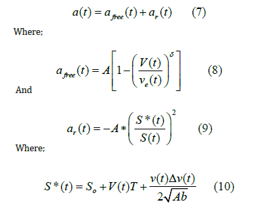
Where a(t) is the acceleration of the vehicle; afree(t) is the free acceleration equation; ar(t) is the congestion deceleration equation; A is the maximum acceleration; v(t) is the vehicle speed at time t; ve is the desired speed; δ is the acceleration index; S*(t) is the expected distance of the driver at time t; s(t) is the distance between the vehicle and front vehicle at time t; So is the static safe distance; T is the safe time interval; Δv(t) is the speed difference between the proceeding vehicle and the leading vehicle at time t; b is the absolute value of comfortable deceleration.

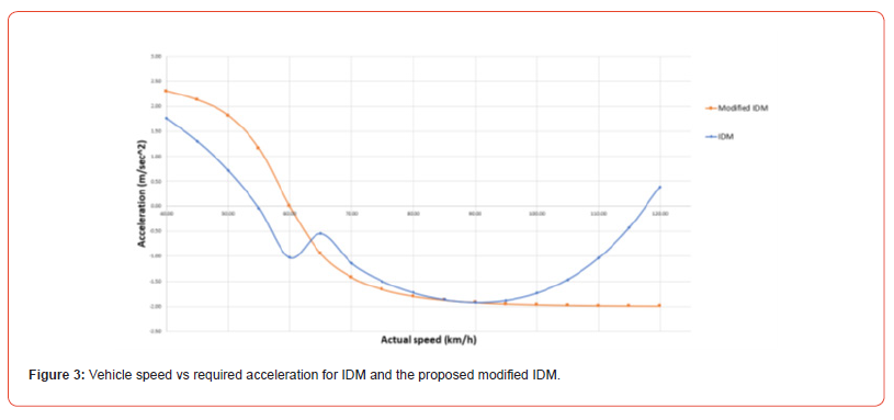
The acceleration control algorithm for different guidance strategies at signalized intersections is built using IDM, considering the order of departures and the driving conditions of the vehicles. Nevertheless, a limitation of this general model has been identified in reference [41]. When the actual speed is similar to the predicted speed, the value of afree(t) will become insignificant, yet the value of ar(t) will still be non-zero. Therefore, when the actual speed gets closer to the desired speed, the actual steady-state equilibrium distance becomes much more extensive than S*(t), as shown in Figure 3.
For the above figure, the desired speed was assumed to be around 60 km/h. It can be noted that acceleration and deceleration values using IDM near the desired speed or when the vehicle drives at a higher speed is unrealistic. The reason behind that falls at the steady-state equilibrium, where the actual speed and net distance are closer to the desired speed and the desired gap distance; accordingly, the acceleration becomes zero. Applying these to IDM will give an unrealistic equation. Therefore, there is a need to modify IDM to overcome these issues.
Equations 11 can substitute equation 8, and 12 and 13 can be used as a substitute to equation 9 as follow:
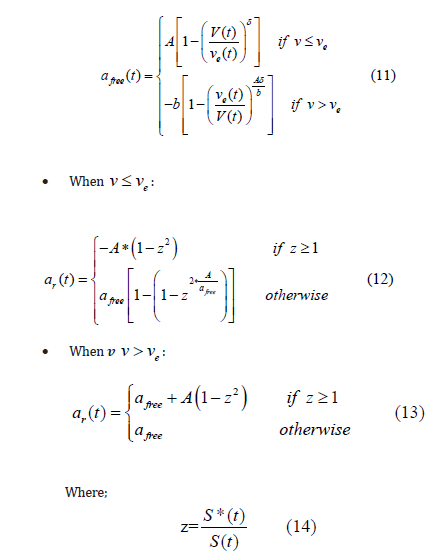
For the driving model b, equation 11 ensures the maximum deceleration rate doesn’t exceed the maximum comfort deceleration. While equations 12 and 13 are used to improve the behavior near the required speed ve(t). As shown in Figure 3, the modified IDM has a more uniform gradual acceleration that doesn’t exceed the maximum deceleration or acceleration. Therefore, the modified IDM was used in the developed algorithm. Using this modified IDM, the CV platoons can adapt to the three scenarios mentioned earlier, changing the value of the desired speed based on the required departure sequence and location of the lead CV. Note that this advisory speed trajectory is sent to the lead CVs only, while follower CVs in the platoon will use different driving models that are not required for the controller to optimize. This step minimizes the controller’s computational effort to accommodate a larger intersection with higher movement volumes.
Simulation
The micro-simulation framework used in this study is discussed with its implementation details in this section. In simulation studies, it is critical to note that two basic conditions must be met in a connected vehicle environment [42]. First, the ability to simulate the road traffic condition and traffic demand. Secondly, establish V2V and V2I communications. Both needs can be met in VISSIM software through some packages. The following subsections illustrate the simulation steps and discuss simulation scenarios used to test the developed algorithm.
Simulation platform
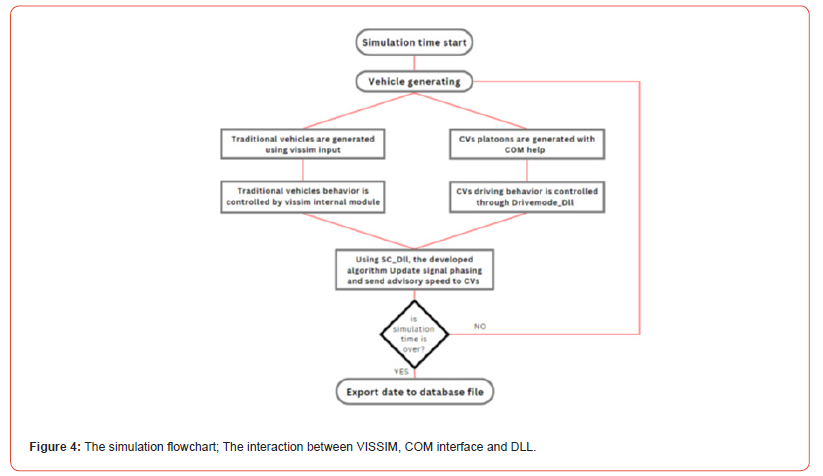
Traffic researchers often rely on VISSIM to simulate traffic signals at intersections. It uses a strong Component Object Model (COM) and Application Programming Interface (API) that enables the creation of communication between vehicles and infrastructure in a connected vehicle setting [43]. “Drivermodel.dll API” and “virtual ASC controller” were utilized to achieve communication between vehicle to vehicle or infrastructure. A C programming language-based program was created using VISSIM-COM to obtain specific vehicle attributes. Furthermore, a Dynamic-Link Library (DLL) was utilized as an External Drive Module (EDM) to interact with the COM interface and act as a “platoons’ generator” to generate various penetration rates and scenarios.
This work intends to develop a traffic micro-simulation model that mimics the existing traffic characteristics. The base model of this study was developed using the procedure outlined in the FDOT Traffic Analysis Handbook [44] to comply with the most scientific approach. Table 7-6 of the FDOT Handbook is a guideline used in the verification process to implement the VISSIM model error checklist. The developed intersection used in VISSIM represents the developed algorithm functionality in dynamic traffic demand. Therefore, at every 15-minute interval during the simulation, varying arrival rates were generated, with the help of the COM interface, to examine the traffic demand fluctuation in real-world scenarios (Figure 4).
Driving behaviors
Types of vehicles used in this study can be categorized into two
main types:
• Traditional vehicles: VISSIM imposes human driving behavior
on conditional vehicles. The simulation software package uses
its internal car-following model (Wiedmann 74) for this type
of vehicle. It was assigned to have a minimum speed of 35 km/
hr and a maximum speed of 50 km/hr with a uniform distribution.
• CVs: the behavior of this type of vehicle is fully controlled with
Dynamic Link Libraries files integrated with VISSIM. For the
lead CV, the lateral movement is controlled by the modified
Intelligent Driving Model (IDM). The advisory speed was trajected
to the lead vehicle and used as the desired speed in IDM.
In addition, only in the developed algorithm do the proceeding
CVs tend to form and keep the platoon in form using equations
(15,16 and 17) [45].
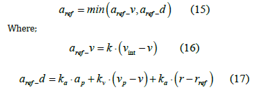
Equation 15 calculates the acceleration needed for the following CVs to catch up with the lead CV upstream, form a platoon and maintain a constant time headway. It takes the smallest value from Equations 16 and 17. In these equations, k = 1, vint represents the intended velocity, and v represents the current velocity of the following CV. ka = 1, while kv and kD values are 0.58 and 0.1, respectively. The variable vp is the velocity of the predecessor CV, and r is the net distance between the two CVs. rref is the maximum value between rmin and rsystem equal to (2) and(0.5 .v), respectively.
Simulation scenarios
Achieving comprehensive and more authentic findings is essential based on sensitive analysis of the study parameters. Therefore, this study focused on finding an optimization algorithm for all kinds of total demand. Unsaturated, where travel demand is less than capacity, and at saturation demands, where travel demand is equal to or greater than capacity, were tested in the simulation scenarios. Different ratios of travel demand to capacity were considered (varying between 0.7 and 1.1). Equation 18 is used to calculate the capacity [44]. Furthermore, four market penetrations of CVs were tested at different levels.

Where s is the saturation flow rate, based on Highway Capacity Manual (HCM), it was assumed to be 1900 pc/hr/ln, g is the effective green time, C is the cycle time, and N represents the number of lanes on each lane group.
Fixed and actuated plans are two widely used signal planes that were compared with the developed platoon-based algorithm. In addition, the individual-based algorithms were included in the comparison as well. The fixed and actuated signal scenarios assumed that CVs could not receive or send vehicle data to the traffic signal controller. On the other hand, CVs in the individual and platoon-based algorithms are capable of vehicle-to-infrastructure communications. However, CVs in individual-based algorithm tends to act as free agents and receive advisory speed guidance based on each CV location and current speed. In contrast, CVs in platoon-based algorithm tends to form platoons utilizing previous equations (15,16 and 17), especially when a platoon joins another platoon with a slow advisory speed.
With four different CVs compositions, four different signal plans, and saturated and under-saturated travel demand compositions, 32 scenarios were tested using VISSIM. In each scenario, a varying 15-min arrival rate was used. Furthermore, the Florida Department of Transportation (FDOT) has recommended using the following equation (19) to determine the minimum number of simulations runs for any simulation’s scenarios [9]:

The minimum number of simulations runs n is determined by using the standard deviation S of previous runs, the critical value tα of the two-sided T-test with a 95% confidence level, the mean μ of previous runs, and an estimated tolerance error ϵ of 10%. To ensure an adequate amount of simulation runs were conducted, equation 19 was used for all performed runs. For instance, when the average vehicle delay was measured at 0.85 vehicle to capacity ratio, it was found that the number of simulations required was (7.11x2.09/49x0.1)-9 Therefore, the number of runs should be ten or more. The maximum required number of runs was found to be twelve among all scenarios, and to be conservative, all the simulations conducted included 20 seed runs.
Results
Average vehicle delay and the total number of stops are the two main performance measures applied to evaluate the developed algorithm. Vehicle delay is a common performance measure under a connected vehicle environment [27]. VISSIM calculates the travel time by subtracting the theoretical travel time without obstacles, such as other vehicles or signal controls, from the actual travel time. On the other hand, the average number of stops is for all vehicles in the network or that have already arrived. Based on [47], a non-dimensional Performance Index (PI) was applied using a transformation strategy to include the abovementioned performance measures. The following equation (20) was applied for each performance measure on all of the 32 conducted scenarios using VISSIM

Where n is the number of simulation replications, and xi is the average performance measure at replication i, divided by the highest performance measure Xmaxi at that replication. Therefore, two measure performance ratios were estimated and summed up for each scenario to calculate its PI as in equation (21). The results of the average PI values for each scenario are illustrated in the subsequent two Figures 5&6.
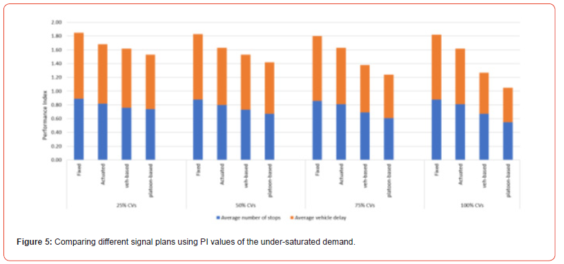
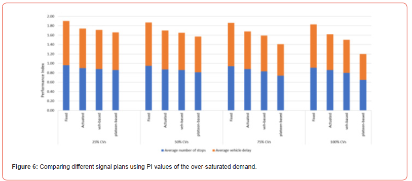
As shown from the two figures above, the PI values of platoon- based and vehicle-based algorithms decrease relative to the traditional signal plans as the percentage of CVs increases. On the one hand, the traditional signal plans keep similar PI values along different percentages of CVs penetration. While on the other hand, the developed algorithm and vehicle-based algorithm have decreasing values as CVs penetration increases. This reduction takes action for both performance measures. Two assumptions were thought to have a significant effect on those reductions. The first assumption is that the advisory speed trajectory has significantly reduced the average number of stops.
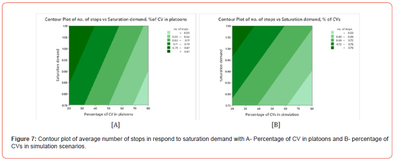
A full factorial experiment was conducted to confirm the initial assumption using the percentage of CVs in simulation, the percentage of CVs in platoons, and saturation demand as variables. The average number of stops was used as the outcome of the experiment. The results, shown in Figures 7A & 7B, indicate that increasing the percentage of CVs in platoons leads to a decrease in the number of stops. This reduction in the average number of stops occurs under both low and high saturation demands. It is since platooning reduces the variation in time between vehicles, allowing more vehicles to pass through traffic signals without stopping [45].
The second assumption states; the equations that control the driving behavior of CVs in platoons are partially responsible for average vehicle delay reduction. As aforementioned, equations (15, 16, and 17) are enforced through DLL to control the driving behavior of CVs in the platoon-based algorithm, while IDM, also through DLL, controls the driving behavior of the vehicle-based algorithm. Therefore, the developed algorithm gives up to 20% lower PI value than the vehicle-based algorithm, especially with high percentages of CVs. This finding is because generated platoons formed minor time headway compared to free agents’ CVs, which increased the roadway’s capacity [46]. To examine the previous assumption, the platoon-based and vehicle-based algorithms were tested at under- saturated and over-saturated demands with 50%, 75%, and 100% of CVs penetration, where IDM controls the driving behavior of all CVs of both algorithms. The outcome shows an insignificant difference between the PI values of all scenarios.
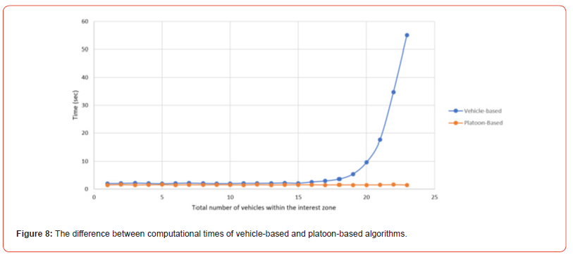
Furthermore, since this study is meant to be expanded to a bigger scale intersection, it was critical to investigate the computational time of the developed algorithm. Two python codes were designed, where both calculate the average vehicle delay to give optimum signal plans and advisory speeds trajectory. However, the first is a vehicle-based algorithm, while the other is a platoon-based one. Both algorithms have a function to measure the computational to run the code and give the optimum signal plan. Both codes were run using the same software package (PyCharm Community Edition, 2.1) and by the same computer, while no other software was active, to not affect the computational time.
Figure 8 illustrates the findings; as can be seen, in the vehicle- based algorithm, the computational time exponentially increases as the number of vehicles within the interest zone increases. The reason behind that is in the vehicle-based algorithm, the number of possible departure sequences increases significantly as the number of vehicles expands in both directions. For instance, if there are ten CVs on the west approach, and another ten on the south approach, there would be more than 180,000 possible departure sequences. While if we increase the number to eleven vehicles on each approach, the number will jump significantly to more than 700,000 possible departure sequences. On the other hand, for the developed algorithm, twenty CVs on an approach would be considered, in computational time, as one CV where equation (6) will be utilized to measure the average vehicle delay of that stopped platoon.
Discussion
Most of the literature on adaptive traffic signal plans under CVs environments outperformed traditional signal plans under saturated demands. However, at over-saturated demands, many researchers have indicated an insignificant difference in performance [49]. The developed platoon-based algorithm has improved by more than 30% compared to traditional signals at under-saturated and over-saturated demands, especially at a high CVs penetration rate. This outcome is because the developed algorithm utilizes the driving behavior of CVs to form platoons with relatively short time headway. It has been proposed that the freeway’s capacity could be significantly enhanced, possibly even doubled or tripled, if all the cars on it were organized into platoons [46]. In addition, the modified IDM has significantly reduced the number of stops. The CVs platoons would attempt to adopt the advisory speed to discharge through the intersection without stopping.
Additionally, the field of adaptive traffic signals for platoons
under connected vehicles is still developing, and there is room for
further exploration. Some possible areas of expansion include, but
are not limited to:
• The algorithm that has been developed could be further improved
by incorporating a more accurate simulation of a fourway
intersection with multiple lanes on each approach and
allowing for all types of vehicle movements.
• The critical headway and spacing thresholds for defining the
platoon need to be investigated and understand their effect on
the algorithm outcome.
• Despite the potential benefits to mobility suggested by several
studies on the use of adaptive traffic control in CVs environment,
there has been limited research on measuring the safety
of intersections in these situations
• Investigating the environmental impact is a critical topic in
modern studies. It is expected that introducing such an adaptive
traffic signal under the CVs’ environment will minimize
the emission of CO2 [50].
Conclusion
This study uses the VISSIM simulation platform to test the developed platoon-based algorithm. The algorithm that has been developed can detect groups of vehicles, including both CVs and traditional vehicles, by utilizing data that is only obtained from the CVs. The signal phasing allocation is then established to optimize the sequences of CVs platoons’ departure to get the lowest average vehicle delay possible. Furthermore, the algorithm also gives advisory speed suggestions to lead vehicles to decrease the average number of times they must stop at the intersection. It was observed that the platoon-based algorithm outperformed the traditional signal plans and vehicle-based algorithm in average vehicle delay. In addition, it provides a significantly shorter computational time compared to the vehicle-based algorithm.
Furthermore, unlike other studies, this study has shown improvement in the performance measures at under-saturated and over-saturated demands. This outcome is due to the short time headway created between the CVs within platoons. Finally, it can be concluded that using the platooning-based algorithm can be favoured by the vehicles-based algorithm. However, there is still an open area to apply and study the platoon-based algorithm in many traffic subjects.
Acknowledgement
Our gratitude and appreciation are to those who have supported and encouraged us through this research. We would also like to thank our friends and family, who have inspired and helped us throughout this project. Their encouragement and unwavering belief in us kept us motivated and focused, and we will forever be grateful for their love and support.
Conflicts of Interest
The authors declare no conflict of interest.
References
- Samimi Abianeh A, Burris M, Talebpour A, Sinha K (2020) The impacts of connected vehicle technology on network-wide traffic operation and fuel consumption under various incident scenarios. Transportation Planning and Technology 43(3): 293-312.
- National Traffic Signal Report (2022) 2012 National Traffic Signal Report Card.
- Kaniz Fatima (2015) Modal congestion management strategies and the influence on operating characteristics of urban corridor. Master, RMIT University, Austrailia.
- Florin R, Olariu S (2015) A survey of vehicular communications for traffic signal optimization. Vehicular Communications 2(2): 70-79.
- Maslekar N, Mouzna J, Boussedjra M, Labiod H (2013) CATS: An adaptive traffic signal system based on car-to-car communication. Journal of Network and Computer Applications 36(5): 1308-1315.
- (2019) Real-Time Control for Intersection Traffic Signals. Doctoral dissertation, Texas A&M University.
- Zheng X, Recker W, Chu L (2010) Optimization of control parameters for adaptive traffic-actuated signal control. Journal of Intelligent Transportation Systems 14(2): 95-108.
- Ekkehard Kohler, Martin Strehler (2018) Traffic Signal Optimization: Combining Static and Dynamic Models. Transportation Science 53(1): 21-41.
- Alzahrani A (2019) The operational and safety effects of heavy-duty vehicles platooning (1). Master’s thesis, University of North Florida.
- Eom M, Kim BI (2020) The traffic signal control problem for intersections: a review. European transport research review 12(1): 1-20.
- Yiheng Feng, K Larry Head, Shayan Khoshmagham, Mehdi Zamanipour (2015) A real-time adaptive signal control in a connected vehicle environment. Transportation Research Part C: Emerging Technologies 55: 460-473.
- Huang, Qingfeng Miller, Ronald (2004) Reliable Wireless Traffic Signal Protocols for Smart Intersections.
- Priemer C, Friedrich B (2009) A decentralized adaptive traffic signal control using V2I communication data. 12th international ieee conference, intelligent transportation systems, pp. 1-6.
- Olia A, Abdelgawad H, Abdulhai B, Razavi SN (2016) Assessing the potential impacts of connected vehicles: mobility, environmental, and safety perspectives. Journal of Intelligent Transportation Systems 20(3): 229-243.
- Liu Z (2007) A survey of intelligence methods in urban traffic signal control. IJCSNS International Journal of Computer Science and Network Security 7(7): 105-112.
- J Rios-Torres, AA Malikopoulos (2017) A Survey on the Coordination of Connected and Automated Vehicles at Intersections and Merging at Highway On-Ramps. in IEEE Transactions on Intelligent Transportation Systems 18(5): 1066-1077.
- Li N, Chen S, Zhu J, Sun DJ (2020) A platoon-based adaptive signal control method with connected vehicle technology. Computational intelligence and neuroscience.
- Day CM, Li H, Richardson LM, Howard J, Platte T, et al. (2017) Detector-Free Optimization of Traffic Signal Offsets with Connected Vehicle Data. Transportation Research Record 2620(1): 54–68.
- Priemer C, Friedrich B (2009) A decentralized adaptive traffic signal control using V2I communication data. 12th international ieee conference, intelligent transportation systems, pp. 1-6.
- Goodall NJ, Smith BL, Park B (2013) Traffic signal control with connected vehicles. Transportation Research Record 2381(1): 65-72.
- Beak B, Head KL, Feng Y (2017) Adaptive coordination based on connected vehicle technology. Transportation Research Record 2619(1): 1-12.
- Cai C, Wang Y, Geers G (2012) Adaptive traffic signal control using wireless communications (No. 12-2998).
- Ahmane M, Abbas-Turki A, Perronnet F, Wu J, El Moudni A, et al. (2013) Modeling and controlling an isolated urban intersection based on cooperative vehicles. Transportation Research Part C: Emerging Technologies 28: 44-62.
- Pandit K, Ghosal D, Zhang HM, Chuah CN (2013) Adaptive traffic signal control with vehicular ad hoc networks. IEEE Transactions on Vehicular Technology 62(4): 1459-1471.
- Wu J, Abbas-Turki A, Correia A, El Moudni A (2007) Discrete intersection signal control. IEEE international conference, service operations and logistics, and informatics, Pp. 1-6.
- (2018) The Usage of the U.S. Environmental Protection Agency. Environmental Protection Agency.
- Kaidi Yang S, Ilgin Guler, Monica Menendez (2016) Isolated intersection control for various levels of vehicle technology: Conventional, connected, and automated vehicles. Transportation Research Part C: Emerging Technologies 72: 109-129.
- S Ilgin Guler, Monica Menendez, Linus Meier (2014) Using connected vehicle technology to improve the efficiency of intersections, Transportation Research Part C: Emerging Technologies 46: 121-131.
- Dresner, Kurt Stone, Peter (2004) Multiagent Traffic Management: A Reservation-Based Intersection Control Mechanism. Proceedings of the Third International Joint Conference on Autonomous Agents and Multiagent Systems 3: 530-537.
- Dresner, Kurt Stone, Peter (2006) Human-usable and emergency vehicle–aware control policies for autonomous intersection management. Pp. 17-25.
- L Li, D Wen, D Yao (2014) A Survey of Traffic Control With Vehicular Communications. in IEEE Transactions on Intelligent Transportation Systems 15(1): 425-432.
- MAS Kamal, JI Imura, T Hayakawa, A Ohata, K Aihara (2015) A Vehicle-Intersection Coordination Scheme for Smooth Flows of Traffic Without Using Traffic Lights. in IEEE Transactions on Intelligent Transportation Systems 16(3): 1136-1147.
- Hausknecht M, Au TC, Stone P (2011) Autonomous intersection management: Multi-intersection optimization. In 2011 IEEE/RSJ International Conference on Intelligent Robots and Systems, pp. 4581-4586.
- Lee S, Oh C, Lee G (2021) Impact of automated truck platooning on the performance of freeway mixed traffic flow. Journal of Advanced Transportation.
- Peng Jing, Huang Hao, Chen Long (2017) An Adaptive Traffic Signal Control in a Connected Vehicle Environment: A Systematic Review. Information (Switzerland) 8(3): 101.
- Yu S, Fu R, Guo Y, Xin Q, Shi Z (2019) Consensus and optimal speed advisory model for mixed traffic at an isolated signalized intersection. Physica A: Statistical Mechanics and its Applications 531: 121789.
- Pokharel P (2018) Development of Platoon-Based Traffic Signal Control System For Arterial Corridor: A Case Study In Houston. Lamar University-Beaumont.
- Zhang Z, Liu F, Wolshon B, Sheng Y (2020) Virtual traffic signals: Safe, rapid, efficient and autonomous driving without traffic control. IEEE Transactions on Intelligent Transportation Systems 22(11): 6954-6966.
- Ma F, Yang Y, Wang J, Li X, Wu G, et al. (2021) Eco-driving-based cooperative adaptive cruise control of connected vehicles platoon at signalized intersections. Transportation Research Part D: Transport and Environment 92: 102746.
- Jiang Y, Li S, Shamo DE (2006) A platoon-based traffic signal timing algorithm for major–minor intersection types. Transportation Research Part B: Methodological 40(7): 543-562.
- Treiber M, Kesting A (2014) Traffic flow dynamics: data, models and simulation. Physics Today 67(3): 54.
- Treiber M, Hennecke A, Helbing D (2000) Congested traffic states in empirical observations and microscopic simulations. Physical review E 62(2): 1805.
- Xiao (Joyce) Liang S. Ilgin Guler, Vikash V Gayah (2020) A heuristic method to optimize generic signal phasing and timing plans at signalized intersections using Connected Vehicle technology, Transportation Research Part C: Emerging Technologies 111: 156-170.
- PTVgroup (2020). The Mind of Movement.
- Florida Departments Of Transportation (2022) TRAFFIC ANALYSIS HANDBOOK. Pp. 1-164.
- Smith SW, Kim Y, Guanetti J, Li R, Firoozi R, et al. (2020) Improving urban traffic throughput with vehicle platooning: Theory and experiments. IEEE Access 8: 141208–141223.
- B van Arem, CJG van Driel, R Visser (2006) The Impact of Cooperative Adaptive Cruise Control on Traffic-Flow Characteristics. in IEEE Transactions on Intelligent Transportation Systems 7(4): 429-436.
- Florida Highway Administration (2017) Simplified Highway Capacity Calculation Method for the Highway Performance Monitoring System. Pp. 1-46.
- Marler RT, Arora JS (2005) Function-transformation methods for multi-objective optimization. Engineering Optimization 37(6): 551-570.
- PD Brummitt, MS Khan (2022) Truck Platooning and Its Impact on Fuel Emissions. 2022 IEEE Green Technologies Conference, GreenTech, pp. 130-135.
-
Ahmed Alzahrani*, Mohammad D Alahmadi, Adel Abu Hashim and Ren Moses. Adaptive Signal Control under Platooned Connected Vehicles Environment: Phase Allocation Optimization Using Platoons Departure and Advisory Speed Trajectory Method. Glob J Eng Sci. 11(1): 2023. GJES.MS.ID.000752.
-
Connected vehicles, Platoon-based algorithm, Individual vehicle-based algorithm, Departure sequence, Trajectory speed advisory
-

This work is licensed under a Creative Commons Attribution-NonCommercial 4.0 International License.


