 Research Article
Temperature Field in a Material Containing Asphalt-Resin-Paraffin Substances in a Microwave Electromagnetic Field
Fatykhov MA, Doctor of physical and mathematical sciences, professor, the head of the department of the general and theoretical physics, Bashkir State Pedagogical University of M. Akmully, Ufa, Russia.
Received Date: October 26, 2020; Published Date: December 04, 2020
Abstract
The relevance of the study is due to the need to develop technological and technical solutions of protecting from paraffin and gas hydrate plugs within the pipelines formed under particular thermohydrodynamic conditions. In this regard, this article is aimed at disclosing the features of heating and melting of such plugs using a super-high-frequency electromagnetic radiation source moving within the pipeline. A theoretical study of temperature change within the “pipeline – plug – environment” system, which allows us to fully consider its interaction with the electromagnetic radiation, is the leading method for studying this problem. A mathematical model has been presented and a theoretical study of the plug electromagnetic heating process for heat exchange on the pipe outer surface according to Newton’s law on the hypothesis that the EM transmitter of Н11 type moves, and the achievement of a complicated configuration of thermal sources and temperature has been disclosed in the article. The materials of the article are of practical value for establishing the initial indices of the paraffin plugs removal technology in a pipeline and oil well when exposed to electromagnetic radiation.
Keywords: Electromagnetic waves; Pipeline; Paraffin deposits
Introduction
There is a tendency to increase the share of hard-to-recover oil reserves in the oil industry at this time. Among these are, in particular, deposits with the oils characterized by high viscosity and content of asphalt-resin-paraffin substances (ARPS), deposits with low-permeability terrigenous and carbonate reservoirs, etc. [1]. Natural thermobaric conditions of the deposits are changing during oil recovery process leading to deposition of ARPS on the walls of the wells and rising pipes, in the pumping equipment and aboveground pipelines. Treatment by chemical reagents (inhibitors, demulsifiers, etc.), magnetic and acoustic fields are used for prevention of ARPS deposits. Thermal methods of ARPS removal, in particular, via the injection of hot-oil or solvent reactants, when interacting with which the exothermic reactions occur, are extensively used. Development of technology and method of paraffin and hydrate formation suppression has an interesting history. However, all the difficulties associated with the solution of this problem have not been overcome by now. A variety of conditions for field development and characteristics of the extracted products requires innovative approaches [2]. Based on the model of paraffins or crystalline hydrates formation due to changes in the thermobaric conditions and mechanical adhesion of deposits to the well walls, removal of ARPS and crystalline hydrates is performed either via feeding various reagents that dissolve the deposits (or warm up their zone) into the well, either via downhole heaters or mechanically using scrapers. Some technologies allow removing the deposits even in the absence of circulation inside the pumping and compression pipe (tubing) [3]. In particular, methanol is added to gas flow to prevent the formation of crystalline hydrates in the gas pipe-line. There are a number of special methods along with the general ones. So, for ex-ample, dehydration of the gas being pumped, the method of pressure relief at the pipeline ends, the application of laser irradiation for generation of molecular levels, and the like are used for crystal hydrate plugs formation prevention. Despite their differences, all mentioned methods have a high cost, are difficult to implement or organization of chemicals production, such as methanol that are toxic ones very often, is required to provide the abovementioned. This state of things makes it necessary to look for new, cheaper and safer methods of preventing the formation and destruction of crystal hydrate and paraffin plugs. The results of the studies performed both in our country and abroad point to the fact that one of the most effective methods for protection from ARPS, which is fundamentally different from traditional ones, is the use of high-frequency (HF) and super-high-frequency (SHF) electromagnetic fields (EMF) energy. In this case, heating, which occurs as a result of conversion of the electromagnetic radiation (ER) energy into the internal energy of the medium in the processes of its polarization, is the most significant effect. The method of protecting from asphalt-resin-paraffin substances (ARPS) in the oil producing wells via HF and SHF EMF energy differs in the fact that the well serves both as a tube through which the oil is extracted to the surface, and as a waveguide or a coaxial line along which the EMF energy is conveyed. The efficiency of this process depends on the electromagnetic power within the well. The maximum power is transferred into the well in case of an equality of the generator and well output wave resistances. The well resistance values depend on the values of the dielectric parameters of the media filling the well, the nature of these values as a function of temperature, phase transitions, the structure of gas-liquid mixture, etc. Wellbores and pipelines are transmission lines (coaxial lines, cylindrical wave-guides) for electromagnetic waves from the standpoint of HF electrodynamics. The phase and group velocities of the electromagnetic waves, their damping is determined by the type of the waves, the material of the pipeline walls and the dielectric properties of hydrocarbons.
Having directed the HF power from the external generator to the plug, it can be heated to the paraffin melting or crystalline hydrate decomposition temperature, and thus an obstacle can be eliminated [4-9]. The volumetric nature is an essential advantage of the plugs heating HF method, since the electromagnetic waves in the HF bandwidth can deeply penetrate into the plug material. Besides, the heating process can be controlled via changing the HF generator power level and the electromagnetic radiation frequency, since the dielectric permeability and the loss-angle tangent of the plug material depends on the radiation frequency and temperature [10]. The processes of paraffin plugs heating and melting within the bores of the oil wells and oil pipelines via powerful electromagnetic radiation in the mode of electromagnetic waves continuous generation have been studied in the paper [11]. The times of the end-to-end channel penetration within the plug and the times of its complete elimination have been determined for selected capacities and frequencies of the HF source taking into account the heterogeneity of the HF power distribution along the borehole section and the ohmic absorption of HF power in the metal walls of the well pipes. Since the metal walls are in thermal contact with the paraffin plug, an additional warming up factor of the paraffin plug appears. Considering the plug heating via the steel walls significantly reduces the paraffin plug penetration time in a number of instances, in particular in case of equipping the oil well bore. The melting process proceeds gradually from the well bore central region to the periphery so that the paraffin molten region has a conical shape. The conical shape of the molten zone can lead to destruction of the plug until it is totally melted. A paraffin plug of 100m long is being completely eliminated with HF generator power of 10kW and an operating frequency value of 10 MHz in 34 hours in the considered numerical examples [12] within a coaxial bore of the oil well equipment. When the power was increased up to 20 kW, the time of plug elimination was shortened down to 12 hours. The analysis of the paraffin plugs elimination process in the oil well bore via a HF power source operating in the mode of periodic turning the power on and off (periodic duty) has also been made. It has been shown by the authors of [12] that in this mode the total time of the plug elimination depends very heavily on the HF source power and onoff ratio of its operation. The total time of the plug meltdown increases non-linearly with on-off ratio increase at a specified power of the HF source. The full (total) operating time of the HF source itself is also increasing with the HF generator operating cycle onoff ratio increase. These regularities are explained by the increase in the thermal losses with on-off ratio increase (HF source shutdown time). It has been established that the full time of the source operation (or the energy expended at a specified power) slightly depends on its operating time within the limits of a single cycle. There is a threshold value of on-off ratio, at which a full penetration of the paraffin plug is never achieved. The oil well is a coaxial transmission line in the electrodynamic sense. Due to peculiarity of the TEM wave dispersion within a coaxial line, the operational frequency optimum value, which corresponds to the HF power absorption coefficient value in the plug equal to the plug inverse length, can always be chosen. The oil pipeline can be considered as a cylindrical waveguide capable of transmitting electromagnetic waves with a frequency higher than the cut-off frequency.
There is a strong absorption of HF power and heating of only a narrow area of the plug adjacent to the HF generator on these frequencies. It has been proposed in the paper [11] to use a moving electromagnetic emitter in order to eliminate the paraffin plugs under these conditions. The speed of its movement shall be determined by the velocity of the liquid-solid interface during paraffin plug melting under the influence of HF electromagnetic emission.
The moving velocity of the HF power source and the time for complete elimination of the plug has been determined. It has been demonstrated that the efficiency of the moving HF source, i.e. the energy fraction expended for paraffin plug melting reaches 70% for the selected parameters of the HF source and paraffin plug. The process of HF purification of paraffin deposits within the oil pipeline at an early stage of their formation has been investigated, when the deposits do not clog the oil pipeline yet. Cleaning is fulfilled via a moving HF source. It has been shown that the time of HF frequency cleaning essentially depends on the value and position of the maximum of heat generation power density. The maximum of heat generation power density shifts from the center to the pipeline wall, where the paraffin layer is localized with frequency increase. The magnitude of the heat generation density maximum value is also increasing. Cleaning time decreases accordingly. The dependence of the oil pipeline cleaning time on the thickness of paraffin deposits is significant only for low HF power levels. The initial oil temperature has a small effect on the HF cleaning time. The processes of paraffin plugs heating and melting in the oil well were considered in the paper before [8]. In this case, the model of the HF field homogeneous distribution over the bore cross section was being used. Besides, ohmic absorption of HF power in the wells walls was not taken into account, which would lead to an additional damping of the electromagnetic emission during its propagation and thus to heating of the walls. In fact, the HF power distribution in the cross section is highly nonuniform in the well for the considered electromagnetic waves of TEM type (cable waves). Consideration of the HF power nonuniform radial distribution leads to qualitative and quantitative features of the plug heating and melting in the wellbore [9]. Besides, an additional damping of TEM waves in the well due to HF power losses in the wellbore walls will be taken into account hereinafter. The dissipation of HF power in the steel walls of the pipes leads to heating of the walls. An additional channel for the plug heating appears due to the fact that the steel walls are in thermal contact with a paraffin plug.
A laboratory facility has been developed in the paper [13] and the investigations of paraffin heating and melting under the influence of the electromagnetic oscillations energy in a short-circuited coaxial system have been conducted. It has been demonstrated that, depending on filling of the intratubular space with paraffin or air, the paraffin melting can occur both as a result of its heating by means of thermal conductivity and owing to occurrence of distributed heat sources within the system under the action of the electromagnetic field. The rate of paraffin heating and melting within a coaxial system is much greater in the latter case than in the former case. These regularities are significantly influenced by the paraffin dielectric properties and the electromagnetic properties of pipe materials. The process of paraffin heating and melting occurs in the field of a standing electromagnetic wave formed due to its reflection from the inhomogeneities of the coaxial line pipes surfaces if all else being equal. Thus, the results obtained in these studies confirm the perspectivity of the well electromagnetic treatment method with a view to remove deposits and increase their throughput. Conversion of EM energy into thermal energy occurs within the range of high-frequency (HF) waves most intensively. The issue is how EM energy can be transferred to the medium intended for this purpose. Not any transmission line can transfer EM waves of any frequency. For example, EM energy is transferred through the coaxial transmission line by means of TEM waves wherein there are no restrictions to frequency. There are critical frequencies within the waveguides below which the EM waves cannot be transferred [14]. Let us suppose that a coaxial transmission line is a well in which tubing and a casing may serve as an inner and an outer wire unless they do not touch each other. If they touch each other then the EM energy can be transferred along the tubing internal cavity. In this case, the tubing is a circular waveguide in the electrodynamical term. The oil pipeline and the gas pipeline are a circular waveguide as well. The waves of the E or H type can propagate within a circular waveguide only [14]. If the oil pipeline has a small radius, EM waves of a very high frequency can propagate within it only, which rapidly decay due to strong ab-sorption of EM energy via the medium. Therefore, the medium is being heated extremely nonuniformly. There may be a severe overheating and big losses of heat to the environment surrounding an oil pipeline at some points. On the contrary, there is heating not sufficient for melting the medium at other points. As a consequence, the destruction of the plug can proceed to a shallow depth only. Destruction of ARPD by means of a moving source of HF EM waves – “EM Mole” is possible under these circumstances. In this method, the source of the HF EM radiation moves while the medium melts and the possibility of movement emerges. The destruction of a dielectric plug, which is paraffin, is more effective. The features of such a method have been partially investigated in the papers [11, 12].
Propagation of several types of waves is possible within the waveguide, but not all of them can easily be excited [14]. Especially this is the case of EM wave source to be pushed deep into the pipeline into a molten medium. It is necessary to research all possible options. In this case, an option of H11 wave propagation within the waveguide with the lowest critical frequency has been considered [14]. The features of propagation of such a wave within a waveguide with electrical losses and phase transitions of the media filling the waveguide are not presented in the literature. The studies of the electromagnetic fields application intended for solving oil and gas production problems have been evolving in recent years in the trends highlighted in the papers [15-20]. A numerical study of the paraffin plugs heating and melting process in the oil pipelines equipment via microwave electromagnetic radiation generated by a super-high-frequency electromagnetic wave of the H11 type is simulated and conducted in this paper.
Research Methods
Alkane hydrates and gas hydrates are dielectrics that are characterized by an integrated relative dielectric constant:

ε is the electrical permittivity of vacuum; E,H- the intensities of the electric and magnetic fields, respectively; E0,H0-their amplitudes depending on the spatial coordinates and time, c,ρ ,λ - specific-heat capacity, density and medium thermal conductivity coefficient, respectively in formulas (2) - (4). The appearance of internal heat sources in such a dielectric, while it interacts with HF EMF and, as a consequence, the change in temperature and pressure within it, makes us possible to use the energy of powerful electromagnetic emission in order to decompose paraffin and gas-hydrate plugs being formed in various units of equipment.
By virtue of equation (4) and assuming that hard deposits have fully clogged the pipeline, the thermal conductivity equation shall be solved as follows:


where P is the EM wave source strength.
The differentiation formula [15] has been used in the expression (11):

The problem is being solved numerically by the level set method without an explicit phase separation. The density and thermal conductivity of oil are considered to be independent of temperature, and the heat capacity has a δ-shaped singularity at the phase transition temperature ТS

A coefficient that shows how much the actual absorbed power differs from the power being set is determined, and then the expression (11) shall be multiplied by this coefficient. H is the length of the paraffin plug in the integral.
The boundary conditions were being accepted to solve the equation (5). The convective heat transfer was being set according to Newton’s law at the plug end z=0:

where Т0 – ambient temperature and the paraffin plug initial temperature; k1 – heat-exchange coefficient.
There is no heat exchange at the remote end of the plug z=Н:

The moving velocity of the EM wave source v along the coordinate z was being set as constant and selected so that there were no zones with an unmelted paraffin behind the source (the value v=1.5 m/h was being used in the calculations).
Results
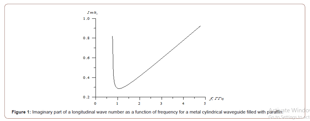
The dependence of the longitudinal wave number z k′′ imaginary part on the EM field frequency is shown in Figure 1 for a cylindrical waveguide with a paraffin plug of the following radius (Figure 1).
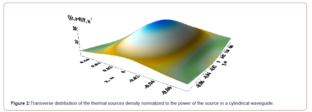
The distribution of the thermal sources Q (r, φ, z=0) density normalized to the EM wave power source is shown in Figure 2 in the waveguide cross section for the frequency f=1.4•109 Hz (Figure 2).
The cylindrical coordinates have been converted into Cartesian ones x, y, z for the convenience of image in the figure. In this case, the circular waveguide is represented as a circle inscribed into rectangle. The symmetry with respect to the right and left, upper and lower halves of the waveguide cross section may be noted according to Figure 2. This makes us possible to consider the processes within a quarter of a circle only and have an idea of what is going throughout the circle. Thus, it is possible to save computer
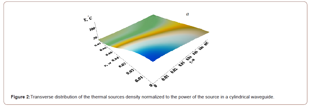
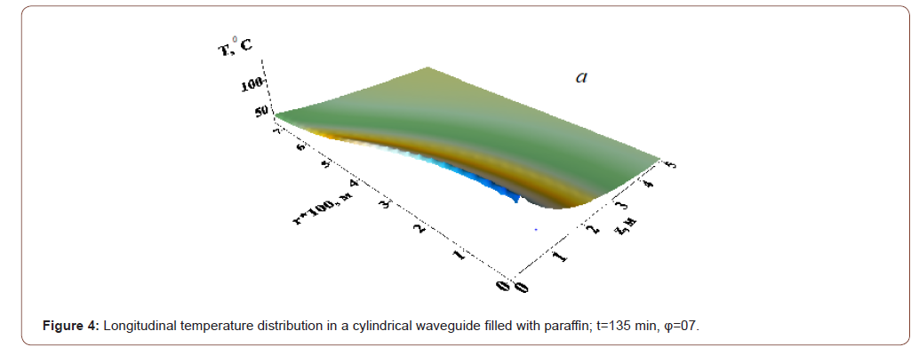
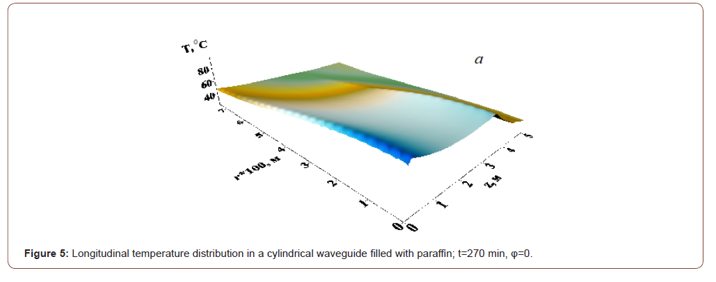
resources in the numerical solution of the problem and consider the processes within the first quadrant only. The results of numerical simulation of a paraffin plug heating and melting process via an “EM Mole” are shown in Figures 3–5 for different moments. When conducting design studies, the following parameters of a high-paraffin crude oil were used: ρ=950 kg/m3; c0=3 kJ/(kg•K); λ=0.125 W/(m•K); L=300 kJ/kg; κ=1.613 W/(m2•K); Nu=1 (pipe in a dry soil); κ1=0.2W/(m2•K); T0=200C; TS=500C; H=5 m; P=6.5 kW;
f=1.4•109 Hz; ε 0′ =2.3; tgδ= 0 0 ε ′′ ε ′ =0.012; σ=3.4•106 Ohm-1•m-1. The problem was being solved by an alternating direction implicit method with a uniform rectangular grid [22]. The delta function in terms of thermal conductivity was being approximated by a step with a half-width equal to 0.40C (Figures 3–5).
Discussion
The critical frequency Н11 of the wave for the considered cylindrical waveguide with radius R=0.0775 m – f0≈0.746•109 Hz. According to Fig. 1, the imaginary part of the longitudinal wave number has a minimum kz′′ ≈0.2874 m-1 on a frequency f≈1.06•109 Hz and grows with a further frequency increase. In this case, the length of the electromagnetic wave penetration into the plug depth is 1.74m, which is sufficient to control the movement of the electromagnetic emitter, although this value is not the matter for this method of paraffin plugs removal. As can be seen from Figure 2, the distribution of heat sources in the waveguide cross section looks like an ellipse because of the dependence on the angle φ. The density of thermal sources also strongly depends on the coordinate r and the stronger the higher the EM wave frequency, i.e. the heat sources distribution in the waveguide cross section is very non-uniform. But this type of wave has an advantage in comparison with the others, i.e. it has the lowest critical frequency, i.e. the deepest heating along the plug may be implemented via it. The maximum of thermal sources is obtained on the waveguide axis, and the thermal sources configuration does not generally depend on the frequency. This also gives an advantage, because the EM wave source is to be located most conveniently at the pipe center. The density of thermal sources falls exponentially lengthwise. The rate of decrease in the heat sources density increases based on the dependence with the frequency increase in the longitudinal direction shown in Figure 1. “EM Mole” began to move in 135 minutes after start of the heating process in Figure 3-4. All values along the coordinate r have been multiplied by 100 in Figure 4 & 5 for convenience of image. As can be seen from the figures, the medium heating process depends heavily on the thermal sources density distribution. The location of the plug initial penetration is completely determined by the peak density of the thermal sources. The temperature distribution in the transverse direction due to medium thermal conductivity and the temperature distribution in the longitudinal direction owing to movement of the “EM mole” becomes more uniform as time goes by. The “EM mole” movement has to be started long period after start of heating time for the sake of melting the plug across the whole pipeline section.
Conclusion
The process of a paraffin plug removal via one of the possible types of waves, which can be excited in a circular waveguide H11, has been considered. The surface separating the solid and liquid phases has an ellipse shape with a cross section decreasing along the plug. Such a shape of a molten zone can lead to destruction of the plug until it is fully melted. If we set a goal of making a hole in the plug along its whole length in order to start oil transportation as soon as possible, rather than melting it all along the entire pipeline’s radius then movement of the “EM mole” can be started much earlier and moved faster. The studies conducted in the present paper have shown that the electromagnetic radiation source must be moved along the pipe at a velocity to be self-consistently determined based on the law of motion of the interfacial area between the solid and liquid phases in order to remove the paraffin plugs within a pipeline via it. The issues considered in this paper are also of scientific and practical interest for solving the problems associated with gas hydrates [23-25], high-viscosity oils and bitumen’s [26-29].
Acknowledgment
The work was supported by the Russian Foundation for Basic Research (grant No. 18-29-24178).
Conflict of interest
No conflict of interest.
References
- Krasnov VA Method and equipment for oil production from the wells complicated by asphaltene deposits.
- Methods of controlling paraffin deposits in flow wells p.425.
- Sorokin AV, Khavkin AYa (2007) Features of ARPD physical and chemical generation mechanism in the wells. Drilling and oil 10: 30-31.
- Makagon YuF (1994) Russia's Contribution to the study of Gas Hydrates. Int conf on natural gas hydrates Annals of the New York Academy of Science 715: 119-145.
- Sayakhov FL, Fatykhov MA, Imashev NSh (1987) Electrical dewaxing of wells. Discoveries Inventions N 20 Inventor's Certificate 1314756 USSR.
- Akhmetov AT, Dyachuk AI, Kislitsyn AA (1992) The method of liquidation of ice, gas and hydrate and paraffin plugs in the flow lines of wells and pipelines. Discovery Inventions N3 Inventor’s Certificate 1707190 / USSR.
- Homer L Spencer, Calgary Gr (1987) Solution of Paraffin Deposition Problems in Oil Wells by Utilization of the Radio-Frequency Single Well Stimulation process.
- Kislitsyn AA (1996) Numerical simulation of high-frequency electromagnetic heating of a dielectric plug filling a pipe. Applied Mechanics and Technical Physics Magazine 37(3): 75-82.
- Balakirev VA, Sotnikov GV, Tkach Yu V, Yatsenko TYu (1999) Microwave method for elimination of paraffin plugs in oil wells. 9th Crimean Exhibition Microwave Engineering and Satellite Telecommunication Technologies 25-27. Sevastopol Ukraine Proceedings of the Conference pp.422-424.
- Chistyakov SI, Denisova NF, Sayakhov FL (1972) Experimental study of the dependence of the dielectric properties of oil and its fractions on frequency. Bulletin of Higher Education Institutes. Oil and gas 5: 53-56.
- Balakirev VA, Sotnikov GV, Tkach Yu V, Yatsenko TYu (2001) Destruction of asphalt-paraffin deposits in oil pipelines via a moving source of high-frequency electromagnetic radiation. Technical Physics Journal 41(9): 1-8.
- Balakirev VA, Sotnikov GV, Tkach Yu V, Yatsenko TYu (2001) Elimination of paraffin plugs in oil wells equipment and oil pipelines via high-frequency electromagnetic radiation. Electromagnetic phenomena 2(3): 7.
- Fatykhov MA (2002) Features of paraffin heating and melting in a coaxial system under the influence of high-frequency electromagnetic radiation. Thermophysics of High Temperatures 40(5): 802-809.
- Semenov NA (1973) Technical Electrodynamics. M: Svyaz p.480.
- Fatykhov MA, Fatykhov LM (2015) Microwave electromagnetic method of melting the paraffin plug in an open coaxial system. J Eng Phys Thermophys 88(3): 724–729.
- Fatykhov MA (2016) Research of the depth of heating of highly viscous dielec-tric liquid under high-frequency electromagnetic field using the method of di-mensional theory. Surface Engineering and Applied Electrochemistry 52(1): 79–84.
- Kovaleva LA, Zinnatullin RR, Mullayanov AI, Shrubkovskii II (2016) Experimental studies of Heating rheologically complex fluids with electromagnetic field. High Temperature 54(4): 612-614.
- Davletbaev A, Kovaleva L, Babadagli T (2016) Combining solvent injection Electromagnetic heating and hydraulic fracturing for multistage heavy oil recovery. Journal of Electromagnetic Waves and Applications 30(2): 207-224.
- Kovaleva L, Musin A (2016) Numerical modeling of heavy hydrocarbon liquid heating. Brazilian Journal of Chemical Engineering 33(1): 169-175.
- Davletbaev AY, Kovaleva LA, Nasyrov NM, Babadagli T (2015) multi-stage hydraulic fracturing and radio-frequency electromagnetic radiation for heavy-oil production. Journal of Unconventional Oil and Gas Resources 12: 15-22.
- Yanke E, Emde F, Lesh F (1964) Special functions (Formulas, graphs, tables). p.344
- Samarsky AA, Gulin AV (1989) Numerical methods. M.: Nauka p.432.
- Makogon YF (2010) Natural gas hydrates – A promising source of energy. J Natural Gas Science and Engineering 2: 1-21.
- Zhao J, Fan Z, Wang B, Dong H, Liu Y, Song Y (2016) Simulation of microwave stimulation for the production of gas methane hydrate sediment. Applied Energy 168: 25-37.
- Shagapov VSh., Chiglintseva AS, Rusinov AA (2016) Theoretical modeling of gas recovery process from a porous gas-hydrate formation partially saturated with gas taking into account the thermal interaction with surrounding rocks. Theoretical foundations of chemical engineering 50(4): 452-462.
- Bera A, Babadagli T (2017) Effect of nature and injected nanoparticles on the efficiency of heavy oil recovery by radio frequency electromagnetic heating. Journal of Petroleum Science and Engineering 153: 244-256.
- Bera A, Babadagli T (2015) Status of electromagnetic heating for enhanced heavy oil/ bitumen recovery and future procpects: a review. Applied Energy 151: 206-226.
- Bera A, Babadagli T (2017) Effect of nature and injected nano-particles on the efficiency of heavy oil recovery by radio frequency electromagnetic heating. Journal of Petroleum Science and Engineering 153: 244-256.
- Khabibullin IL, Nazmutdinov FF, Vakhitova NK (2017) Simulation of heating dielectric media by electromagnetic radiation in nonlinear mode. Journal of Applied and Industrial Mathematics 11(1): 82-87.
-
Fatykhov MA. Temperature Field in a Material Containing Asphalt-Resin-Paraffin Substances in a Microwave Electromagnetic Field. Cur Trends Civil & Struct Eng. 6(4): 2020. CTCSE.MS.ID.000645.
-
Electromagnetic waves, Pipeline, Paraffin deposits, Asphalt-resin-paraffin substances, Inhibitors, Demulsifiers, Crystal hydrate plugs
-

This work is licensed under a Creative Commons Attribution-NonCommercial 4.0 International License.


