


 Research Article
Prediction of Lateral Confinement Stress for Concrete Filled Steel Tube Column
Received Date: October 21, 2019; Published Date: October 29, 2019
Abstract
Structural columns that are made up of two or more different materials are known as composite columns. Studying composite structures is beneficial since it is a new and modern way to build structures and benefit from materials in a different way. Concrete- filled steel tubular structures makes the composite column a very stiff, more ductile, cost effective (as compared to reinforced concrete structures) and consequently a structurally efficient member in building and bridge constructions. In this study a numerical simulation of a circular composite column was conducted. In order to achieve the study objectives, Finite Element Method (FEM) based software (ABAQUS) was used due to many advantages including saving time of the calculation and providing a simulation of the behavior of the member. A load-deflection curve of a circular composite column was plotted by considering the stress-strain curve of normal concrete and compared with the experimental results. It was found that the load capacity was less than that of experimental results. The reason of this underestimation was the confinement effect. A correction factor for lateral confining pressure of 1.5 was found for circular sections since the equation used for confining pressure obtain from literature was applicable to square composite columns.
Introduction
Concrete-filled steel tubular columns (CFT) are effective in earthquake- resistance, structures subjected to impact, and highrise buildings columns. Due to the increasing use of composite columns, various researches have been carried out in recent years. In 1998, Schneider SPE [1] conducted an experimental and analytical study on the behavior of short, concrete-filled steel tube columns concentrically loaded in compression to failure. In 2003 Shosuke Morino & Keigo Tsuda [2] introduced the structural system and discuss advantages, research findings, and recent construction trends of the CFT column systems in Japan. The paper also described design recommendations for the design of compression members, beam-columns, and beam-to-column connections in the CFT column system. In 2014, Hsuan-Teh Hu et al. [3] proposed and verified proper material constitutive models for (CFT) columns. In 2014 Ananya John et al. [4] presented analytical study on stress-strain behavior of reinforced concrete column by modelling concrete and steel part separately. In this paper an analytical study on stress- strain behavior of CFT column was conducted. The finite element-based software used to conduct the analytical study was ABAQUS. The results were validated using the available experimental data.
Material Properties and Constitutive Models
The cross section of the CFT column in this study is modeled the same way it was used in the experimental study. The geometry and material properties are shown in Table 1. To predict the load– deformation relationships of CFT columns, an accurate constitutive model for steel and confined concrete is needed.
Constitutive model for Steel tube
The steel properties are shown in Table 1. The stress-strain curve used for the steel tube is assumed to be elastic-perfectly plastic.
Table 1: Geometry and material properties of concrete filled steel tube column.

Constitutive model for Concrete
The concrete properties are shown in Table 1. The compression stress-strain curve used for the concrete is the Modified Hognestad model presented by Belharbi & Hsu [5] shown in Figure 1. The tensile stress-strain curve used for the concrete is shown in Figure 2 (Table 1) (Figures 1,2).


Methodology
Various computer packages are available nowadays and finite element analysis can be done with high accuracy. ABAQUS was chosen to model a CFT column the same way it was used in the experimental study. A fixed boundary condition is applied to one end of the modeled CFT column shown in Figure 3 (Figure 3).

Result
A load-deflection curve of normal concrete excluding the confinement effect was plotted and compared with the experimental study Figure 4. As shown in Figure 4, the maximum load that causes a 30mm deflection in the ABAQUS model is less than the experimental study maximum load. These kinds of results were expected since the confinement effect was not considered. Therefore, the application of the confinement effect is necessary to produce realistic and similar results to the experimental study (Figure 4).

Therefore, to apply the confinement effect, the stress-strain model of the confined concrete had to be used. Mander et al. [6] presented a stress–strain relation of confined concrete as shown below.
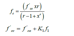
(k1 is a function of the concrete mix and the lateral pressure, a value of 4.1 can be used as per Mander et al. [6]).
Where:
 compressive strength of confined concrete,
= longitudinal compressive concrete strain,
compressive strength of confined concrete,
= longitudinal compressive concrete strain,
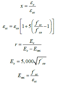
 and
and  = the
unconfined concrete strength and corresponding strain, Ec =
Young’s modulus of concrete,
= the
unconfined concrete strength and corresponding strain, Ec =
Young’s modulus of concrete,  = (secant) Young’s modulus of
concrete (approximately 0.7-0.85Ec).
= (secant) Young’s modulus of
concrete (approximately 0.7-0.85Ec).
The confining pressure for a square section was presented by Lingola et al. [7] as following:
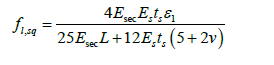
Where:
Es = Young’s modulus for the steel wall, ts= the thickness of the
steel wall, L = the half length of a side of the square cross- section,
ν = Poisson ratio (dilation ratio) at failure. ν was fixed equal to
0.2. While more refined evaluations can be based on the iterative
evaluation of 
Since the Eq. 8 was applicable for square sections only, a correction factor of 1.5 was found by Hit-and-Trial procedure. Therefore, the lateral stress 𝑓𝑙 for circular column is:
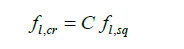
Where: 
To apply Eq. (1), a value of the confining pressure fl had to be
found. fl is a function of different variables including εl which is
unknown. Therefore, to find a reasonable and an applicable value
of εl, εcu was considered instead of εcc assuming that the ultimate
strain of the normal concrete approximately equals the peak strain
of the confined concrete. The value of εl was found to be 0.006 and
accordingly 
Hence, the stress-strain model of confined concrete for C1 was found as shown in Figure 5 below (Figure 5).
As noted in Figure 5 the peak stress of the concrete was increased. Therefore, to improve the results obtained from normal concrete in Figure 5, the effect of confined concrete was applied to the model.

Hence, a load-deflection curve for the CFT column was plotted as shown in Figure 6 (Figure 6).
As it can be noted in Figure 6, the load- deflection curve obtained from ABAQUS was improved comparing to the experimental curve due to applying the effect of confinement. Additionally, including the effect of confinement increased the load capacity of the columns.

Conclusion
The following conclusions are made based on the results of this study:
1. A load-deflection curve of a circular composite column was plotted by considering the stress- strain curve of normal concrete and compared with the experimental results. It was found that the load capacity was less than that of experimental results. The reason of this underestimation was the confinement effect.
2. A correction factor for lateral confining pressure of 1.5 was found for circular sections since the equation used for confining pressure was applicable to square sections.
Acknowledgement
None.
Conflict of Interest
No conflict of interest.
References
- Schneider S (1998) Axially Loaded Concrete-Filled Steel Tubes. Journal of Structural Engineering, ASCE, p.10.
- Shosuke M, Keigo T (2003) Design and Construction of Concrete-Filled Steel Tube Column System in Japan. p.23.
- Hu HT, Huang CS, Wu MH, Wu YM (2014) Nonlinear Analysis of Axially Loaded Concrete-Filled Tube. ASCE p.8.
- Ananya John, Unni Kartha G and Prof S Usha (2014) Analytical study on stress-strain behaviour. Journal Impact Factor, 5(12): 45-55.
- Belarbi Zhang Lx, Hsu TT (1996) Constitutive laws of Reinforced Concrete Membrane Elements. World Conference on Eathquake Engineering 30: 545.
- Mander JB, Priestley JM, Park R (1988) Theoretical stress-strain model. ASCE, p.23.
- Lingola GP, Prota A, Gaetano M (2014) Simplified Modeling of Rectangular Concrete Cross-Sections. mdpi, p.20.
-

This work is licensed under a Creative Commons Attribution-NonCommercial 4.0 International License.


