


 Review Article
Experimental Investigation of Crane Overturning Behavior Using Ultra-Small Model with Emphasis on Boom Angle and Load Height Effects
Received Date:August 03, 2026; Published Date:September 16, 2026
Abstract
This study investigates the overturning load and deformation characteristics of mobile cranes by systematically varying the boom inclination
angle, supporting-base stiffness, and load height. For this purpose, two experiments were conducted: Experiment A examined the combined effects
of boom inclination and base stiffness, whereas Experiment B maintained a constant working radius while varying the load height to isolate its
influence on overturning stability.
The results indicate that the overturning load decreases significantly as the supporting-base stiffness diminishes, demonstrating that ground
softness is the primary factor governing crane stability. In contrast, structural instability becomes more pronounced at smaller boom inclination
angles (i.e., when the boom is closer to the vertical position) and higher centers of gravity, though its static contribution remains smaller than that
of the overturning moment. However, dynamic considerations suggest that a higher center of gravity amplifies inertial moments, further reducing
the overturning load on soft ground.
Consequently, even at an identical working radius, cranes operating with smaller boom inclination angles and greater load heights are more
susceptible to overturning under dynamic disturbances. These findings underscore that crane stability evaluations must extend beyond static
moment equilibrium to account for structural instability and dynamic inertial effects, particularly during operations on soft ground.
Keywords:Crane Toppling; Pile Driver Toppling; Overturning Mechanism; Structural Instability; Overturning Experiment; Model Experiment; Effect of initial Boom Inclination
Introduction
In Japan, the safety of cranes is regulated under the Industrial Safety and Health Act and the Ordinance on Safety of Cranes, and safety against toppling is ensured through the establishment of rated loads and the installation of various safety devices. There is the statement in its technical document regarding repeated toppling accidents of cranes and pile drivers: “Although the operating conditions were such that overturning should not have occurred according to the static equilibrium relationship, 19.5% of the accidents resulted in overturning. …”. [1] This suggests that the overturning safety of cranes cannot be fully ensured solely by evaluating rated loads and working radii.
The overturning stability of cranes and pile drivers are mainly based on static equilibrium analyses and the evaluation of critical loads [2]. In contrast, the present authors have pursued studies based on the viewpoint that structural instability may be involved in toppling accidents that are difficult to explain solely by static equilibrium [3-6]. Their studies have also included analyses that take dynamic effects and ground conditions into consideration [7,8].
In this context, an experimental study using an ultra-small-scale model was recently conducted [9]. In that study, experiments were performed by varying the conditions such as the stiffness of the supporting base, the boom inclination angle and the lifting height of the suspended load; and their effects on overturning behavior were investigated. The results show that crane overturning is governed primarily by the magnitude of the overturning moment and the ground supporting capability, whereas the influence of structural instability is secondary; however, its effect becomes more pronounced as the boom inclination angle with respect to the vertical axis decreases (near-upright) and as the supporting ground becomes softer. Because the study was based on experimentally obtained data, it is considered to have advanced the understanding of crane overturning behavior on soft ground, which had been difficult to clarify through real crane operation.
Though the previous overturning experiments covered a wide range of test conditions, some aspects of the measurement accuracy were insufficient [9]. Accordingly, the present study improves the measurement accuracy and focuses specifically on the effects of boom inclination angle and load height on the overturning mechanism. Using the same ultra-small-scale model as in the previous study, two types of experiments were carried out. In Experiment A, the overturning load was determined while varying the boom inclination angle and the stiffness of the supporting base; and their effects on the overturning mechanism were investigated. In Experiment B, the working radius (overturning moment) was kept constant, while the initial boom inclination angle, thus lifting height of the suspended load, was varied to investigate its influence on the overturning load. Based on the results of these two experiments, the effects of structural instability, which are considered to be involved in unexpected toppling accidents, are discussed.
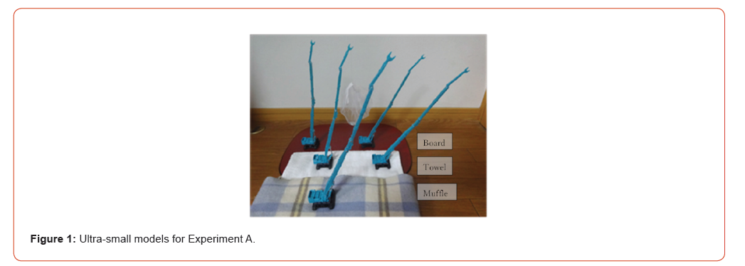
Table:1Specifications of ultra-small models.

Figure 1 shows the appearance of the ultra-small-scale model (Tomica miniature) and the supporting base used in the experiments, and Table 1 summarizes their specifications. The original machine was a demolition machine dedicated to building dismantling, and therefore differs slightly from an ordinary crane in the shape of the boom tip. In addition, the boom is non-telescopic, and the exact locations of the boom rotation center and the center of gravity of the model could not be determined accurately. Nevertheless, the fundamental structure is similar to that of an actual crane.
With regard to the weight distribution, the upper boom is made of lightweight plastic, whereas the lower machine body is made of metal, so the overall distribution is considered to be close to that of a real crane. Accordingly, the model is considered to have sufficient capability for investigating the effects on overturning behavior, which is the objective of the present study.
Experiment A: Overturning Test to Investigate the Effect of Boom Inclination Angle
Outline of Experiment A and Summary of Results
The purpose of Experiment A is to investigate the relationship between structural instability and boom inclination angle in the overturning mechanism of a crane. The initial boom inclination angle (measured from the vertical axis) was varied to five values: 0θ= 10.6°, 16.4°, 24.0°, 30.4°, and 37.3° as shown in Figure 1. Five ultra-small-scale models were prepared with the boom fixed at each of these inclination angles.
Four types of supporting bases were used in order of decreasing stiffness: a board, a single towel placed on the board, four folded towels, and a muffler, which are shown in Figure 1. The lifting load was applied at the boom tip because it was considered that the influence of structural instability would become more pronounced when the boom length was larger and the load application point was higher [9].
As in the previous experiment [9], the load was applied as statically as possible by placing coins, paper clips, etc., in an extremely lightweight bag. Measurements were made using a kitchen scale capable of displaying values to 0.1 g. The boom inclination angle was calculated from the measured height and the working radius of the load point using a tape measure. Thus, as in the previous study, all measurements except the mass measurement were performed using analog methods.
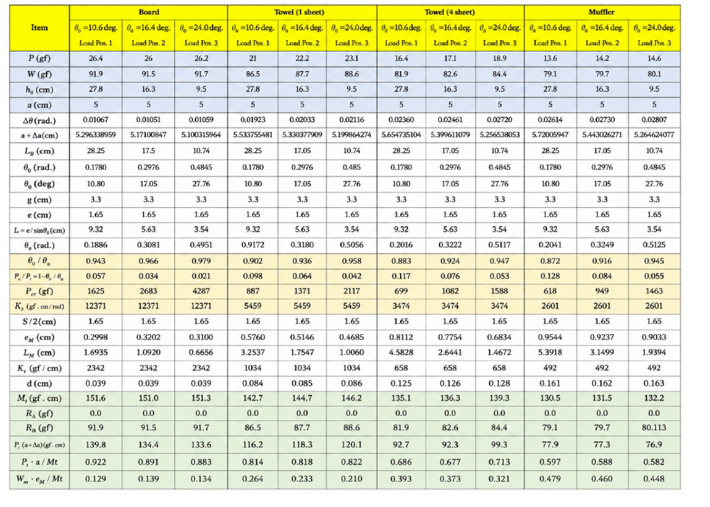
Table 2 summarizes the results of Experiment A. The blueshaded cells in the upper part of the table represent the measured values, whereas the remaining entries indicate prescribed values and numerical analysis results. The symbols used in the table are briefly defined below it; there the structural model adapts a simple rigid bar-rotational spring system. Detailed definitions and calculation procedures are the same as those described in References [6] and [9] and should be consulted for further information. All moments were calculated using the geometry and dimensions before deformation.
Discussion Based on Overturning Load and Overturning Moment
Figure 2-1 plots the relationship between the overturning load (Pt) and the initial boom inclination angle ( 0θ) based on the experimental results shown in Table 2. As expected, the overturning load decreases as the supporting base becomes softer and as the initial boom inclination angle (working radius) becomes larger. It should be noted that the boom inclination angle, working radius, and load height are mutually related. Specifically, a smaller boom inclination angle corresponds to a smaller working radius and a greater load height.
Table:2Results of Experiment A.
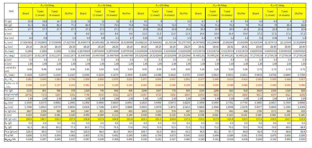
Pt= overturning load; Wt = total weight immediately before overturning; hθ = load-point height before deformation; h1 = load-point
height after deformation (immediately before overturning);
a= working radius; Δa = horizontal displacement immediately before overturning;
LB = boom length from the support point to the load point; 0θ
= initial boom inclination angle;
g= horizontal distance of the center of gravity immediately before overturning (= crawler spacing);
S= distance between crawler centers; e= horizontal distance of the center of gravity from the crawler center immediately before
overturning (= one-half of the crawler center distance, S / 2 );
L= boom length immediately before overturning (distance from the support point to the center of gravity);
θu = overturning inclination angle; u P = total load immediately before overturning (= Wt );
Pcr = elastic critical load (= Ks / L);Ks = rotational spring stiffness;
eM = horizontal distance of the crane gravity center from the crawler center immediately before overturning;
LM = boom length immediately before overturning (distance from the support point to the crane gravity center); Kv = coefficient of subgrade reaction; d= stiffness of the supporting ground (= RB / Kv );
Mt = moment due to the total load; RA = reaction force of the left crawler;
RB = reaction force of the right crawler; Pt ⋅a = overturning moment produced by the overturning load.
Previous experimental results [9] show that a stiffer supporting base produces a smaller change in boom inclination angle under loading, resulting in a clear boundary between stable and overturning states. This is attributed to the phenomenon that, on a stiff base, the crane overturns with little deformation in a socalled overturning-moment-type failure [5]. Accordingly, Figure 2-2 presents the ratio of the overturning load for each supporting base, taking the overturning load on the board support (where deformation is small) as the reference value. The figure indicates that the overturning load ratio decreases significantly as the supporting base becomes softer. Furthermore, when classified by the initial boom inclination angle, the reduction ratio becomes larger for smaller inclination angles. These tendencies are presumed to arise from the influence of structural instability.
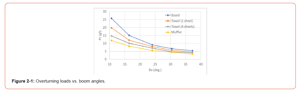
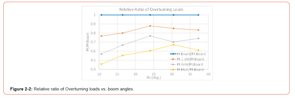
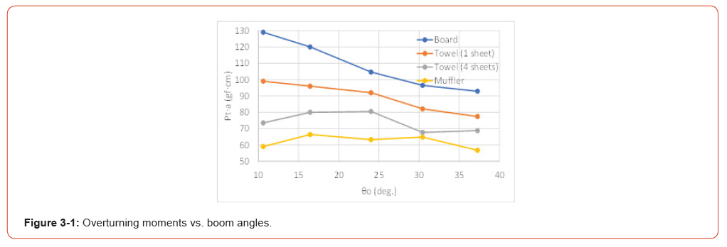
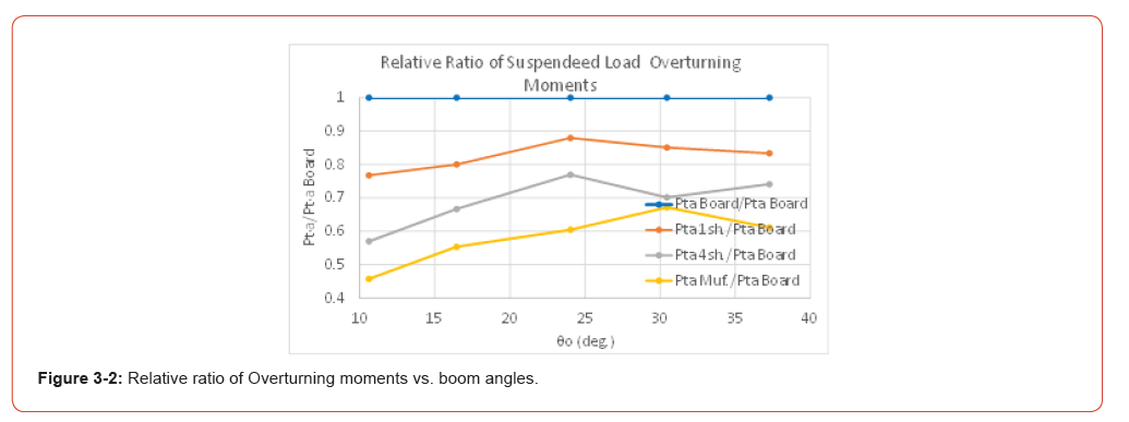
Figure 3-1 shows the relationship between the overturning moment produced by the overturning load and the initial boom inclination angle. The trend for each supporting base is clearly different from that observed for the overturning load in Figure 2-1. This difference arises because the vertical axis in Figure 3-1 represents the overturning load moment ( Pt ⋅a ), which is obtained by multiplying the overturning load by different working radii (a). In particular, for the stiff supporting base, the overturning load moment increases as the boom inclination angle decreases, whereas for the soft ground it decreases.
For a given supporting base, the overturning moment shown in Figure 3-1 might be expected to remain constant regardless of the boom inclination angle under purely static conditions. Possible reasons why this is not the case include the use of the undeformed geometry in the calculations, the assumption that the support point coincides with the boom rotation center, and measurement errors.
Figure 3-2 presents the relative ratios for each supporting base, taking the overturning moment of the stiff board support as the reference. Since the overturning load moment is calculated as Pt ⋅a , and the working radius a is fixed by the position of the load point, Figure 3-2 is identical to Figure 2-2.
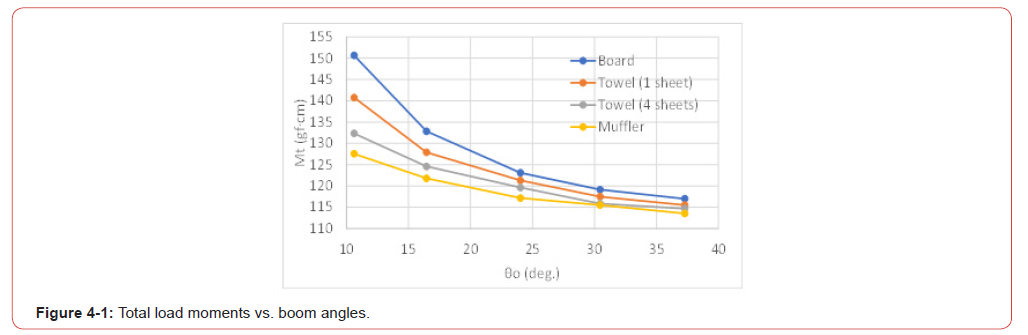
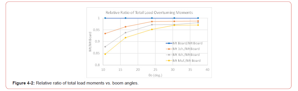
Figure 4-1 shows the relationship between the total load moment and the initial boom inclination angle. The total load moment ( Mt ) is defined as the sum of the overturning moment due to the suspended load at overturning ( Pt ⋅a ) and the overturning moment due to the crane self-weight ( WM. eM ). The total load moment is consistent with the overturning criterion that overturning occurs when the total load moment exceeds the resisting moment ( Mt >Wt ⋅ S/ 2 ). Consequently, the relationship between the total load moment and the boom inclination angle shown in Figure 4-1 has the same general shape as the overturning load–boom inclination angle relationship shown in Figure 2-1.
Figure 4-2 shows the relative ratios with respect to the board support, as in the previous figures. It is evident that, unlike the previous relative ratios, the results vary with the initial boom inclination angle, and the relative ratio becomes smaller when the initial boom inclination angle is small. This indicates that, in the case of the overturning load Pt (Figure 2-2), the difference in supporting-base stiffness is the dominant factor, whereas when the total load ( WM. or Pu ) is involved (Figure 4-2), both the supportingbase stiffness and the initial boom inclination angle have significant effects. According to Figure 4-2, when the boom inclination angle (working radius) is small, the difference in supporting-base stiffness has a large influence, whereas when the boom inclination angle (working radius) is large, its influence becomes relatively small. One possible explanation is that a large boom inclination angle results in behavior closer to an overturning-moment-type failure, whereas a small boom inclination angle enhances the influence of a structural-instability-type failure [5]. Such overturning behavior may be related to unexpected toppling accidents.
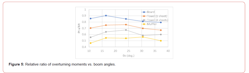
Figure 5 shows the relationship between the ratio of the overturning load moment of Figure 3-1 to the total load moment of Figure 4-1, namely ( Pt.a/Mt ), and the initial boom inclination angle. From an overall viewpoint, this ratio is approximately constant for each supporting base. In particular, as the supporting base becomes softer, the trend approaches the relationship between the overturning moment and the boom inclination angle shown in Figure 3-1. A closer examination reveals that normalization by the total load moment causes the ratio to decrease slightly in the range of small boom inclination angles (small working radii).
Discussion Based on Supporting-Base Stiffness and Deformation
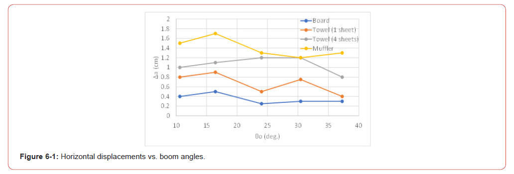
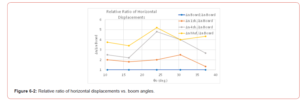
Figure 6-1 shows the relationship between the horizontal displacement immediately before overturning, Δa (measured value), and the initial boom inclination angle 0θ . As expected, the horizontal displacement increases as the supporting base becomes softer. However, for changes in the boom inclination angle, the displacement is approximately constant for each supporting base. Figure 6-2 presents the relative ratios using the board support as the reference, and considerable scatter is observed for the soft supporting bases and large inclination angle.
The horizontal displacement was measured analogically using a ruler, and therefore its accuracy is limited. In particular, for soft bases, there were ambiguities associated with the difficulty of applying the load quasi-statically and with slight variations in the overturning load depending on the contact position of the model. Although the overturning loads were obtained through such trial-and-error measurements, they are considered sufficient for identifying the overall tendencies of the overturning mechanism.
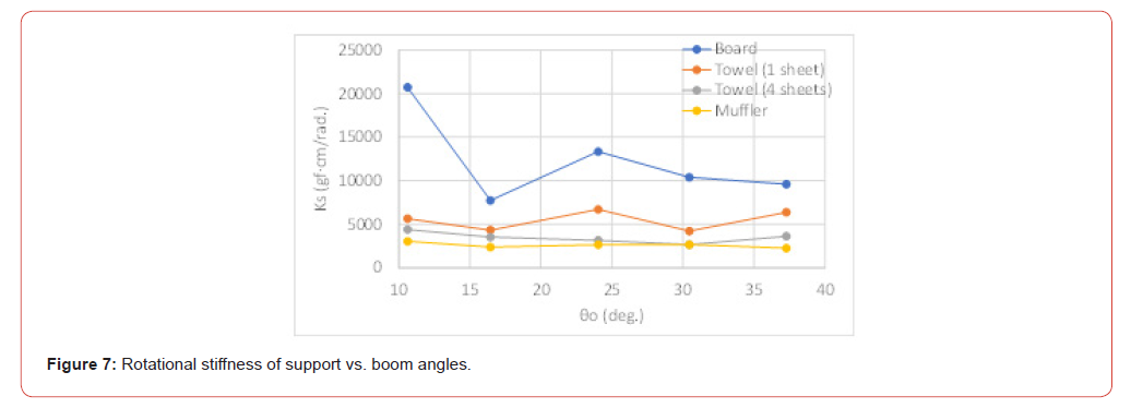
Figure 7 shows the relationship between the rotational spring stiffness Ks and the initial boom inclination angle, where the rotational spring stiffness was calculated using the horizontal displacement Δa listed in Table 2. The rotational spring stiffness s K was obtained analytically from the relation Ks= Pcr ⋅ L together with Eq. (1) presented in the following section. According to Figure 7, the rotational spring stiffness exhibits considerable scatter for the stiff board support, whereas it remains nearly constant for the soft supports. Furthermore, the average values generally correspond to the relative stiffness of each supporting base. Since the rotational spring stiffness of the support is represented here by a simple linear rotational spring model, further investigation is required to clarify its relationship with the actual ground stiffness encountered in real field conditions.
Discussion Based on the Overturning Contribution Ratio
The results of Experiment A presented thus far have shown that the influence of the supporting base is very significant. On the other hand, with respect to the effect of the boom inclination angle, it is found that when the inclination angle (working radius) decreases, the overturning load and overturning moment tend to become smaller on soft bases when expressed as relative ratios to those on the stiff supporting base. Previous experimental results [9] demonstrated that this tendency becomes particularly evident in the overturning contribution ratio associated with the overturning moment. Therefore, the results of Experiment A are further analyzed in detail from the viewpoint of the overturning contribution ratio [5].
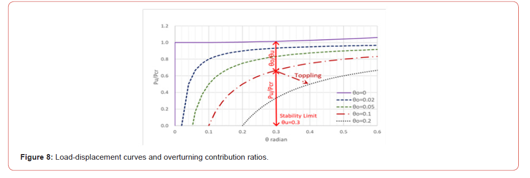
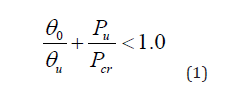
To explain the relationship of the overturning contribution ratio, consider the load-displacement angle curves (static analysis) shown in Figure 8 [6]. A crane overturns when the displacement angle (θ ) exceeds the overturning inclination angle ( θu ), and the limiting state is represented by the intersection of the two as shown in Figure 8. The ratios on the vertical axis at this intersection correspond to the contribution ratio of the overturning moment ( 0θ / θu) and the contribution ratio of structural instability ( Pu/ Pcr ). This overturning condition is expressed as follows [5,6]:
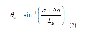
In Experiment A, the overturning inclination angle θu was calculated from the measured horizontal displacement Δa and the prescribed working radius a using the following equation:
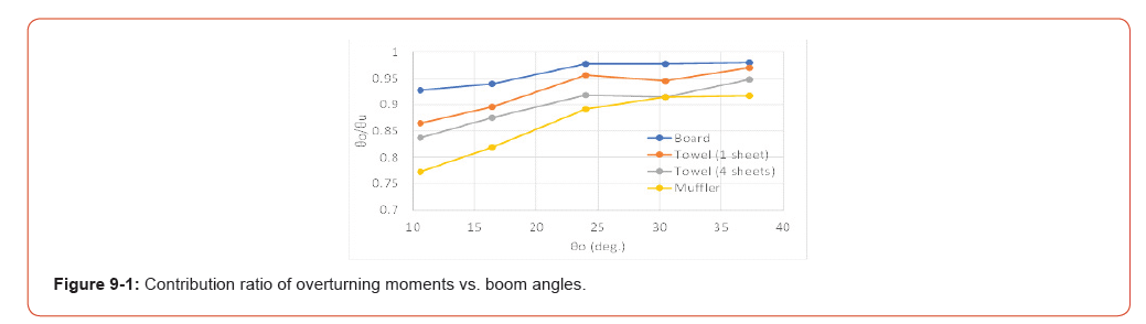
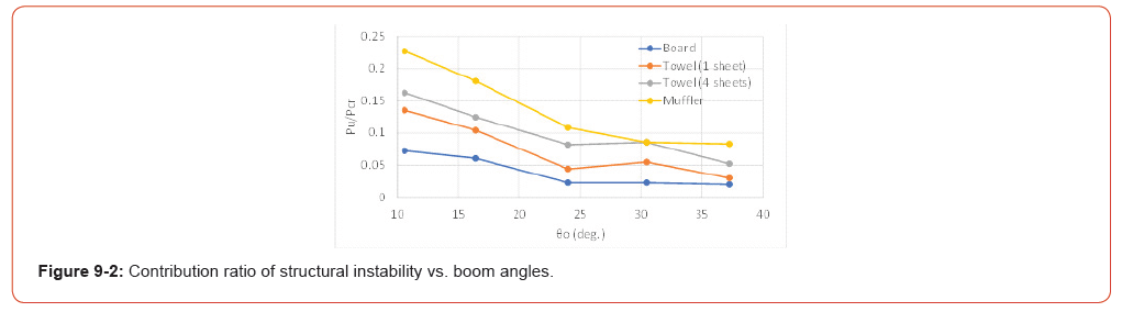
The overturning behavior is discussed below using the overturning condition given by Eq. (1) [5,6]. Based on the results of Experiment A shown in Table 2, the overturning contribution ratio due to the overturning moment, corresponding to the first term of Eq. (1), θθ / θu , is plotted in Figure 9-1. Similarly, the overturning contribution ratio due to structural instability, corresponding to the second term, Pu/ Pcr , is plotted in Figure 9-2. The sums of the both contribution ratios in Figures 9-1 and 9-2 become unity.
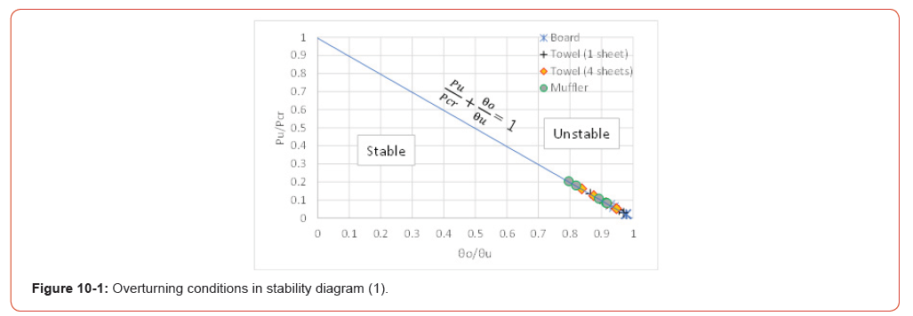
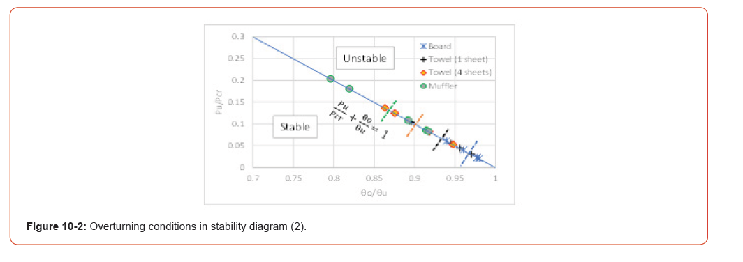
The stability diagram obtained by plotting Eq. (1) using the data in Table 2 is shown in Figure 10-1, and an enlarged view is presented in Figure 10-2. These figures show that the experimental results are concentrated in the lower-right region, which indicate that the contribution ratio of the overturning moment ( θθ / θu ) is overwhelmingly larger than that of structural instability ( Pu/ Pcr ). Therefore, toppling occurs primarily due to the overturning moment, while structural instability, which is related to the degree of deformation, can be regarded as a secondary factor.
However, as noted previously, when the boom inclination angle decreases, the overturning contribution ratio of the overturning moment tends to decrease, whereas the contribution ratio of structural instability tends to increase. An enlarged view of Figure 10-2 shows the average value for each supporting base by a dashed line; as the supporting base becomes weaker, the contribution of structural instability increases, and the variability of the measured values becomes larger. This tendency should be carefully considered to investigate the cause of unexpected toppling accidents.
Experiment B: Overturning Test to Investigate the Effect of Load Height (Constant Working Radius)
Outline of Experiment B and Summary of Results
In Experiment A, the load was applied at the boom tip varying the boom inclination angle, and therefore the influence of the lifting load height could not be clearly identified. In Experiment B, the effect of the lifting load height was investigated by keeping the working radius constant (a=5 cm) while varying the lifting height of the suspended load. Maintaining a constant working radius also means that, for the same suspended load, the overturning moment does not change even if the lifting height is varied.
Figure 11 shows photographs of the three ultra-small-scale models used in Experiment B. These models correspond to the three models with the smallest boom inclination angles used in Experiment A. To maintain a constant working radius, the positions of load points 2 and 3 were determined by suspending a string vertically from load point 1 of the model of θθ =10.60 in Experiment A, as shown in Figure 11. As can be seen from the figure, the boom inclination angles differ among load points 1, 2, and 3.
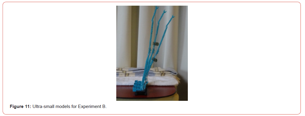
The supporting bases were the same as those used in Experiment A: a board, one towel, four folded towels, and a muffler, arranged in order of decreasing stiffness. Table 3 summarizes the results of Experiment B. As in Table 2, the blue-shaded cells in the upper part represent measured values, whereas the remaining entries are prescribed values or calculated values. It should be noted that, unlike Experiment A (Table 2), in which the horizontal displacement Δa was measured directly, Experiment B (Table 3) uses the average values of the rotational spring stiffness obtained from Experiment A to calculate the displacement angle Δθ (see Eq. (3) presented later).
Discussion Based on Overturning Load and Load Height
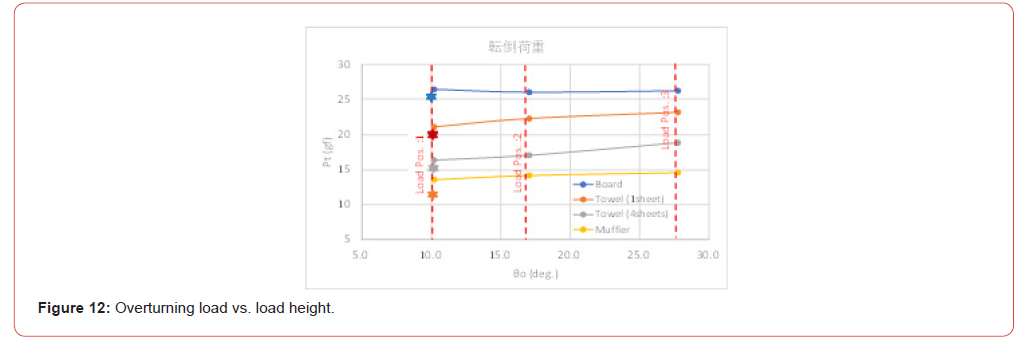
Figure 12 plots the relationship between the overturning load Pt and the load height (load application point) based on the experimental results in Table 3. Although the horizontal axis represents the boom inclination angle, it also indicates the load application point and thus the load height. Since the working radius is kept constant, the overturning moment (excluding the difference caused by the boom inclination angle itself) can be regarded as approximately the same. Consequently, the overturning loads for each supporting base are nearly equal.
However, a more detailed examination reveals that, on the softer supporting bases, the overturning load tends to decrease slightly as the boom inclination angle becomes smaller, that is, as the load height becomes greater. Therefore, the experimental results indicate that, when operating at the same working radius, a lower load height (i.e., a larger boom inclination angle) is preferable from the viewpoint of overturning stability.
Table:3Results of Experiment A.
Load point 1 in Experiment B shown in Figure 12 corresponds to the same experimental condition as 0θ =10.6θ in Experiment A shown in Figure 2-1 (and Table 2). The result of Experiment A for this condition is indicated in Figure 12 by the symbol ☆ for comparison. The figure shows that there is almost no difference for the stiff board support, which exhibits an overturning-moment-type failure [5]. However, as the supporting base becomes softer, the overturning load obtained in Experiment A becomes smaller than that obtained in Experiment B.
Although the experimental conditions are nominally identical, the reduction in overturning load for the softer bases is considered to be a reproducibility issue arising from slight differences in the supporting-base conditions between the separate Experiments A and B. This may be related to the increased uncertainty associated with deformation in the overturning mechanism, as well as the possible influence of dynamic inertial forces discussed later. Nevertheless, Experiments A and B were each conducted systematically, and consistency within each experiment is considered to have been maintained.
Discussion Based on Displacement Angle
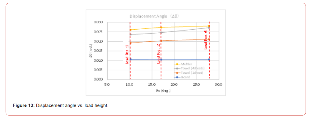
Next, the relationship between deformation (displacement angle) and the lifting load height is examined. As the supporting base becomes softer, the displacement angle Δθ naturally increases, and the calculated values are plotted in Figure 13. The displacement angle was determined using the following equation:
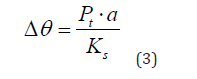
In Eq. (3), the rotational spring stiffness Ks was taken as the average value for each supporting base obtained from Experiment A (see the Ks values listed in Tables 2 and 3). Consequently, the displacement angle Δθ in Figure 13 becomes approximately constant for each supporting base regardless of the boom inclination angle. Because a larger rotational spring stiffness results in a smaller displacement angle, the magnitude relationship of the displacement angle in Figure 13 is opposite to that of the overturning load in Figure 12, although both figures exhibit the same overall trend.
As shown in Figure 7, the rotational spring stiffness exhibits considerable scatter, particularly for the stiff board support. In principle, the rotational spring stiffness should be determined by the stiffness of the supporting base and should therefore take the same value for the same supporting material. For this reason, the average value was adopted here in the calculation of the displacement angle.
By adding the displacement angle Δθ obtained from Eq. (3) to the initial boom inclination angle 0θ , the overturning inclination angle 0u can be calculated as follows:
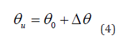
In Experiment B, the overturning inclination angle 0u was calculated using Eq. (4), whereas in Experiment A it was determined using Eq. (2). Although both equations represent the same physical concept, the comparison at load point 1 in Figure 12 shows that as seen before the overturning load obtained in Experiment A tends to be smaller. The same tendency is observed in the subsequent comparisons discussed later. Possible reasons include not only the reproducibility issues associated with experiments on soft supporting bases, but also the difference in the calculation methods used for the overturning inclination angle in the two experiments.
The overturning inclination angle 0u obtained in this manner was then used to evaluate overturning safety according to Eq. (1).
Discussion Based on Overturning Moment
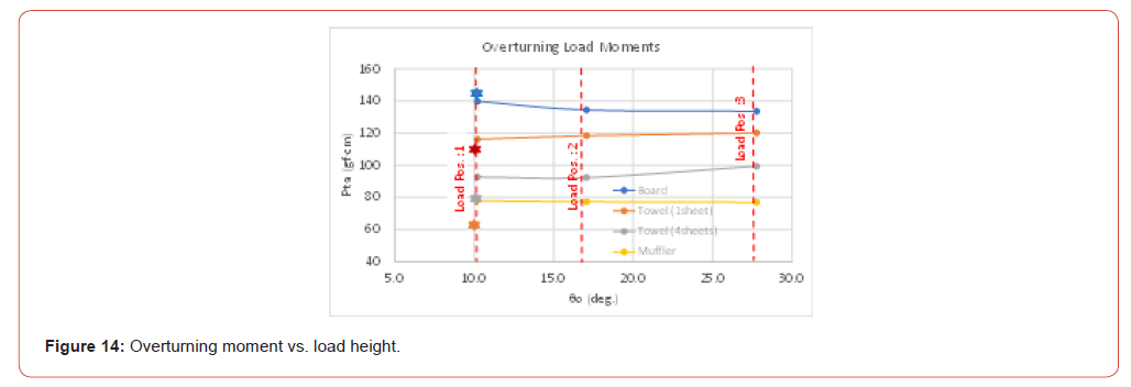
Figure 14 shows the relationship between the overturning load moment and the load height. The overturning load moment was calculated as Pt ⋅a , where the working radius a is the value before deformation, as in Experiment A. Because the working radius a is constant in Experiment B, the graph of the overturning load moment Pt ⋅a has the same shape as the graph of the overturning load Pt shown in Figure 12. The results of Experiment A at load point 1 are also compared in Figure 14, and they show the same tendency as in Figure 12, namely that the values are smaller than those obtained in Experiment B.
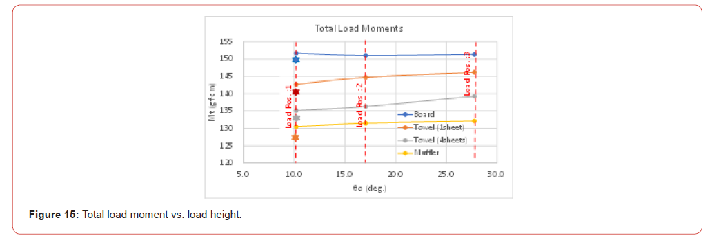
Figure 15 shows the relationship between the total load moment and the load height. The total load moment was calculated from
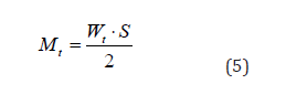
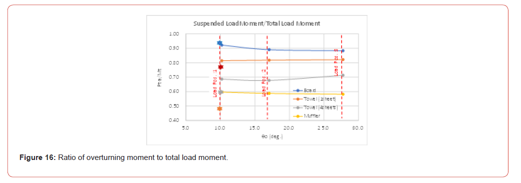
Figure 16 shows the relationship between the ratio of overturning load moment to total load moment and the load height. In all of the figures related to overturning moments (Figures 15, 16, and 17), the same tendency as that of the overturning load in Figure 12 can be observed. In other words, because the working radius is constant in Experiment B, all overturning moments take nearly constant values for the same supporting base.
Discussion Based on the Overturning Contribution Ratio
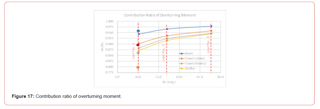
Figure 17 shows the relationship between the overturning moment contribution ratio ( θθ / θu )(the first term of Eq. (1)) and the load height. The figure indicates that the higher load position (load point 1) has a lower contribution ratio of the overturning moment and a higher contribution ratio of structural instability. The results at load point 1 of Experiment A are also plotted in the figure; however, the overturning moment contribution ratio is considerably lower than would be expected from the same overturning conditions between Experiments A and B. The main reason is thought to be the difference in the calculation method of the overturning inclination angle θu between Experiment A [Eq. (2)] and Experiment B [Eq. (4)]. Specifically, Experiment A uses measured values of the horizontal displacement Δa , whereas Experiment B uses analytically obtained values of the deformation rotation angle Δθ caused by the suspended load. Although a substantial quantitative difference is observed, the qualitative tendency is the same for all supporting bases: the greater the load height, the smaller the contribution ratio of the overturning moment and the larger the contribution ratio of structural instability.
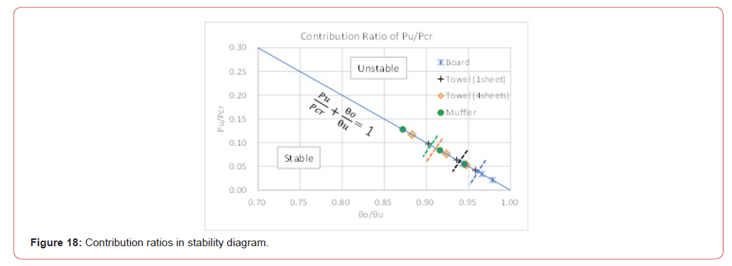
Figure 18 plots the relationship of the two contribution ratios on the overturning behavior diagram according to Eq. (1), (θθ / θu+Pu/ Pcr =1 ), based on the results of Experiment B. Compared with Figure 10-2, which presents the results of Experiment A, the variability observed on the soft supporting base is smaller. It should be noted that experiment A was conducted using five models (Figure 1), whereas experiment B was conducted later using three models (Figure 11) with improved measurement accuracy. Nevertheless, the overall qualitative tendency remains the same.
Dynamic Inertial Forces in Overturning Behavior
The preceding discussions have been based entirely on static experimental results. They showed that the primary cause of toppling accidents is unexpectedly soft ground, while structural instability is a secondary factor that becomes more significant when the center of gravity is high and the support stiffness is soft. In this section, dynamic inertial forces are considered as an additional factor that can strongly influence overturning behavior. The equation of motion including dynamic effects is expressed as follows [7,8]:

where I is the mass moment of inertia (second moment of mass), γ is the damping coefficient, and T is the first moment of the weight.
In Eq. (6), the first term represents the inertial moment, the second term the damping moment, the third term the overturning moment caused by inclination, and the fourth term the restoring moment due to the ground reaction force. In general, the overturning stability of cranes is evaluated under static or quasistatic conditions, considering only the force equilibrium between the third and fourth terms. In dynamic analysis, the first and second terms are additionally included.
Even in the present experiments conducted under nominally static conditions, visual observations indicated that dynamic inertial forces had a significant influence that could not be represented solely by the numerical values obtained from the static experiments. For highly compliant supporting bases, it became difficult to apply the load completely statically, and the determination of the overturning load sometimes varied slightly. This suggests that the dynamic inertial force represented by the first term of Eq. (6) has a substantial effect on the overturning mechanism.
Dynamic actions caused by an increase in suspended load, boom slewing, travelling motion, or local ground settlement generate inertial forces. Because dynamic inertial forces involve the inertial moment, an increase in the height of the center of gravity has a greater significance than that implied by static considerations alone. The dynamic inertial moment (2nd-order moment) is proportional to the square of the height of the center of gravity, and therefore the influence of the center-of-gravity height becomes greater than in static analysis based on the 1st-order moment [7]. For example, when a boom with uniformly distributed mass is converted into an equivalent concentrated-mass system, its center of gravity is located at the midpoint in terms of the first moment, whereas for the second moment it is located above the midpoint. This effect becomes particularly important for box-shaped booms with relatively large mass. According to the present experiments, phenomena that appear to be related to dynamic inertial forces were observed under conditions of soft ground, high center of gravity, and small boom inclination angle.
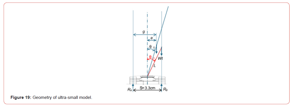
Figure 19 illustrates the geometric conditions of crane at overturning [9]. Under static conditions, toppling occurs when the total crane weight Wt passes beyond the reaction point RB . As the initial boom inclination angle θθ decreases, the overturning inclination angle θu also decreases, resulting in an increase in the member length L. The member length L, which represents the center-of-gravity position of the entire structural system, has a significant influence on structural instability. Furthermore, within the range of the present experiments, the initial boom inclination angle θθ and the overturning inclination angle θu are close in value. Consequently, the contribution ratio of the overturning moment, θθ / θu , is overwhelmingly larger than the contribution ratio of structural instability, Pu/ Pcr (see Eq. (1)). As shown in Figures 9-2, the contribution ratio of structural instability Pu/ Pcr increases as the initial boom inclination angle θθ decreases.
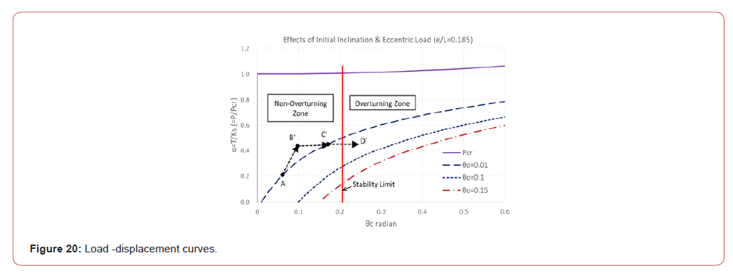
To examine the influence of dynamic inertial forces on overturning behavior, consider the load–displacement angle curve (static equilibrium curve) shown in Figure 20 [8]. When dynamic inertial forces are generated during crane operation, the maximum displacement angle becomes larger than the static equilibrium angle. Suppose that a crane initially in static equilibrium at point A moves to an unbalanced state at point B′ for various reasons. It then tends to return toward the equilibrium point C′ . However, if inertial forces without damping act during this motion, the response overshoots the equilibrium point C′ and reaches point D′ . If this maximum displacement at D′ exceeds the overturning displacement angle θu , toppling occurs.
Possible causes of the transition from point A to point B′ include an increase in suspended load, boom slewing, movement onto an inclined surface or soft ground, and oscillation during travelling. Such disturbances are difficult to eliminate completely during crane operation. Moreover, the theoretical risk of toppling increases as the center of gravity becomes higher, that is, as the initial boom inclination angle θ0 becomes smaller.
From the above discussion, when the working radius is the same, the overturning load may be considered approximately identical under static conditions regardless of the boom inclination angle. Under dynamic conditions, however, a smaller boom inclination angle (measured from the vertical axis) results in a higher center of gravity, leading to larger inertial forces and a greater tendency to overturn. Therefore, in case of the same overturning moment, a larger boom inclination angle (corresponding to a lower load height and a shorter boom length) reduces the overturning risk.
Conclusion
In this study, two overturning experiments using an ultrasmall- scale model were conducted to investigate the influence of structural instability on the overturning behavior of cranes and pile drivers. In Experiment A, five models were used, and the overturning load and deformation were measured while varying the stiffness of the supporting base and the boom inclination angle. The experimental results were presented quantitatively, and the effects of overturning moment and supporting-base stiffness on the overturning mechanism were analyzed. The results showed that the influence of structural instability becomes more pronounced as the boom inclination angle decreases and as the supporting base becomes softer; however, its magnitude is smaller than the influence of the supporting-base stiffness. Therefore, the primary cause of toppling can be attributed to the softness of the supporting base.
In Experiment B, three models were used, and the working radius was kept constant (i.e., the overturning moment was maintained at the same level) to analyze the effect of load height. It is generally recognized that a higher center of gravity leads to greater instability. The experimental results showed that, under static conditions, the overturning load is approximately the same regardless of load height when the supporting base is identical. However, under dynamic conditions, it was theoretically demonstrated that an increase in center-of-gravity height on soft ground reduces the overturning load through inertial forces, and the experiments exhibited the same tendency. The observed tendency was consistent with the intuitive understanding that elevating the center of gravity increases the likelihood of instability.
In actual unexpected toppling accidents, the softness of the ground appears to have been overlooked, resulting in ground failure at the support points. The influence of structural instability is small on firm ground but becomes larger as the ground becomes softer. Overturning stability should therefore be evaluated not only by comparing the static overturning moment with the resisting moment, but also by considering structural instability factors that include dynamic inertial forces, which may contribute to unexpected toppling accidents.
The present experiments involve several simplifications: the ultra-small-scale model was tested with a boom slewing direction fixed at 90°, the loading was static, the boom rotation center was assumed to coincide with the support point, and the analysis employed a simplified rigid-bar–rotational-spring structural model. Accordingly, more detailed investigations are required in future studies. In addition, it is necessary to examine whether the data obtained from the ultra-small-scale model experiments can be applied to actual large-scale cranes.
Acknowledgements
None.
Conflict of Interest
No conflict of interest.
References
- Tamate S, Hori T (2015) A Study on Safety Practices of Investigation of Bearing Capacity of Supporting Ground for Prevention of Overturning of Heavy Machineries, Technical Document of the National Institute of Occupational Safety and Health. JNIOSH-TD-No.3 (2015), National Institute of Occupational Safety and Health, Japan.
- Tamate S, Hori T (2009) 17. Bearing Capacity Factors at Construction Sites Affecting the Overturning of Pile Drivers. Proceedings of the 2009 Symposium on Construction Execution and Construction Machinery, 2009 (in Japanese).
- Toma S, Chen WF (2022) Overturning Mechanisms of Jacks, Cranes and Pile Driving Machines. Structural Engineering International (SEI) 2022, Taylor & Francis Online, 29 July 2022, Scientific Paper pp. 1-9.
- Toma S, Chen WF (2022) Some Aspects of Overturning Mechanisms of Pile Driving Machine on Soft Foundation. American Journal of Civil Engineering 10(6): 225-232.
- Toma S, Chen WF (2025) A Study on Safety Criteria for Toppling of Pile Drivers and Cranes Based on Structural Stability. Archives of Advanced Engineering Science 3 (2): 93-99.
- Toma S, Chen WF (2025) Numerical Study on Toppling Mechanisms of Crane and Pile Driver Based on Structural Stability Theory. Archives of Advanced Engineering Science.
- Toma S, Seto K, Chen WF (2023) Dynamic Analysis for Overturning of Pile Driving Machine on Soft Ground. Transactions on Engineering and Computer Sciences 11(2): 61-81.
- Toma S, Seto K, Chen WF (2024) Comparisons of Static and Dynamic Analyses on Toppling Behaviors of Pile Driving Machinery, etc., on Soft Foundation. Archives of Advanced Engineering Science 2(3): 150-159.
- Toma S, Chen WF (2025) Experiments and Numerical Analysis of Crane Toppling Using Ultra-Small Model. Current Trends in Civil & Structural Engineering 12(2): 1-24
-

This work is licensed under a Creative Commons Attribution-NonCommercial 4.0 International License.