 Research Article
Controlling the Lateral Drift Using Hydraulic Systems
Charles Maroun Khadige1 and Michel Farid Khouri2*
1Faculty of Engineering, Lebanese University, Hadath, Lebanon
2Department of Civil Engineering, Branch II, Lebanese University, Roumieh, Lebanon
Michel Farid Khouri, Department of Civil Engineering, Branch II, Lebanese University, Roumieh, Lebanon.
Received Date: June 22, 2022; Published Date: July 12, 2022
Abstract
Current trends in the construction industry require tall building mainly due to lack of space. Several techniques are becoming available nowadays that are capable of reducing structural vibrations. One of these is the use of tuned liquid dampers (TLD); they are made of water tank(s) generally placed on the top of a building; they use the sloshing energy of water to reduce the dynamic vibration of a structure. This study investigates the use of TLDs and shows their effectiveness in reducing the seismic response of buildings subjected to horizontal acceleration. Multiple analyses were carried out to evaluate the effect of various parameters influencing the performance of TLDs. Analyses were conducted by varying the number of stories, mass and depth ratios. The structural response is then compared to other vibration reduction methods based on the maximum lateral drift. A method to model TLD in ETABS18 software is proposed and a step-by-step procedure to design TLDs is suggested. This procedure can be used by engineers and designers to design TLDs to reduce lateral displacements of buildings.
Keywords: Tall building; Structural vibration; Tuned liquid dampers; Seismic response; Displacement; Drift
Introduction
Earthquakes have prompted engineers to handle the vulnerability of existing structures. Improvement of their seismic performance has become crucial to protect lives, minimize losses and improve safety under seismic loads [1]. The traditional approach for a seismic design is based on the ductile behavior of a structure that dissipates energy through plastic deformations. However, the negative side is that during a high-intensity earthquake, the structure gets damaged and requires high cost of repair. Some damages are severe enough to require the demolishing of a structure [2]. Many investigators have worked on the reduction of lateral drift. Khouri evaluated drift based on elastic structures [3] and suggested a method to reduce lateral drift using springs placed at critical locations in a structure [4]. Dissipating earthquake energy is an efficient way to control the seismic response of buildings. Systems that use this technique are called Seismic Control Systems; they can be active, semi active, passive or hybrid (Figure 1).
Figure 1 presents a passive control device; its performance is based on energy transformation. Such devices are passive in the sense that they do not require any additional source of energy in order to operate. The only source of energy needed is the seismic energy; this type of energy dissipaters is observed in Base Isolators, Oscillators and Dampers.
Dynamic oscillators are dynamic vibration absorbers that are used to dissipate energy of a structure during seismic activities. Tuned Liquid Damper (TLD) and Tuned Mass Damper (TMD) are examples of such oscillators; they are attached to a structural system and become an integral part of it. During vibration, they work in and out of phase with respect to the main structure, thus imparting opposite inertial forces to the induced vibrating forces [5] (Figure 2).

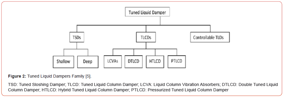
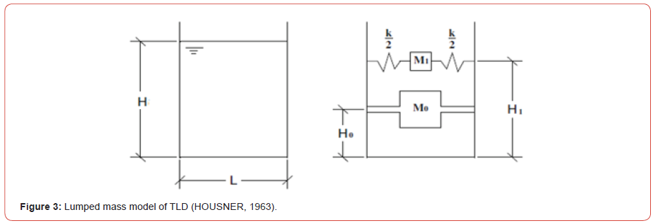
Tuned sloshing Dampers or TSDs are commonly passive control devices that are used in vast range of applications of high-rise structures and bridges [6]. TLDs family presented in Figure 2 are liquid containing tanks that can be placed on existing structures as well as on newly constructed ones. The liquid can be water or other fluids, and the tanks are dimensioned in a way to tune the liquid sloshing to a specific frequency. A typical TLD is presented in Figure 3; it is commonly referred to as TSD; This model was suggested by Housner [11]. These types of dampers are mainly of two types, shallow and deep. Their classification depends on the water height to length ratio H/L, where:
H = Height of water in the tank
L = Width of the water tank in the direction of the water sloshing
(Figure 3).
When H/L < 0.15, TSDs are considered shallow otherwise they are classified as deep [5].
The advantage of TLDs is that they do not require a threshold excitation to be effective. This attribute, associated with their cost effectiveness, make them optimal devices that control structural vibrations [7]. In addition, TLDs have low installation, maintenance, and operation cost; they are easy to install in buildings with no restrictions to unidirectional vibration [8]. The global mechanism of controlling lateral excitation in any structure with TLDs system is about fluid sloshing and wave breaking [9]. What is important is that the energy caused by earthquakes will be dissipated. Moreover, for efficient energy dissipation, the fundamental sloshing frequency of the fluid in the TLD should be close to the fundamental natural frequency of the structure. The sloshing movement of the liquid, caused by structural vibrations, dissipates a significant amount of the energy released by the dynamic forces and thus increases the damping effectiveness of the building [10]. Housner presented a simplified dynamic analysis for the response of elevated water tanks in response to ground motion [11]. Also, [16,19] presented a simplified step-by-step procedure to evaluate hydrodynamic forces in circular and rectangular storage tanks. As presented in Figure 3, water was represented by a convective mass M1 at an elevation H1 from the ground and attached to springs with stiffness K, and by an impulsive mass M0 at an elevation H0 from the ground that is rigidly attached to the tank.
According to Aakash et al [15], the results for a Time History analysis with an excitation force having a period equal to the fundamental period of the building, showed that a TLD can contribute to about 43% reduction in displacement. However, for a Response Spectrum Analysis, TLDs contributed to about 19% reduction in displacement, and the damping effectiveness of TLDs increased with the number of floors. The optimal mass ratio between the TLDs and the building was 2% and the recommended water depth ratio was about 0.2 - 0.3 [15]. The use of TSDs altered the fundamental period of the building from 5s before to 5.29s after installation. The maximum acceleration response at the roof was reduced by 75%. In addition, TSDs provided damping more than 3% [17]. The number of water tanks required for a 20-story building was 200 tanks of size (1.979m x 1.979m x 0.612m) requiring a water height of 0.336 m [15]. Also, [1] found that for a mass ratio of 2.5%, the required number of tanks was 24,000 squared tanks having the dimension of (0.3m x 0.3m x 0.04m). The height of TLD was irrelevant as literature did not propose height limitation due to the fact that water height over the tank’s width did not exceed 0.2 [1]. In the aim to suppress wind-induced vibration of tall building, [17] found that the number of water tanks required for a 40-story building was 290 circular tanks of 3ft in diameter and 5ft high requiring a water height of 3ft. It was also shown by [9] that sloshing dampers can effectively decrease the displacement of buildings when the fundamental period of the structure and the sloshing period are synchronized. In this study, TLDs are modeled using the finite element method to evaluate their efficiency, and to study the characteristics of the sloshing behavior. A 3D-model of the building is evaluated in terms of seismic safety with and without TLDs, in order to determine their contribution to the structure. A parametric study is performed, and displacement reduction equations are generated. Also, a step-by-step design procedure that can be used by engineers and designers is suggested.
Modeling TLDs
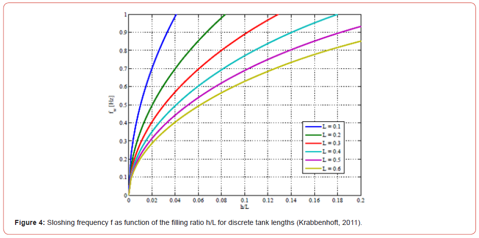
Simulation and modeling of liquid sloshing is well-known, and several methods and strategies have been used; these methods depend on the shape of the liquid tank, the depth ratio H/L and the sloshing frequency. Figure 4 shows the sloshing frequency as a function of H/L for various Tank lengths [12]. The geometry of the tuned liquid dampers used in this study, were chosen to be squared in shape and the parameters that decided the modeling strategy were the depth ratio as well as the mass ratio (Figure 4).
Problem and modeling
The problem is analyzed by studying 5 different buildings, with reinforced concrete shear walls as the lateral load resisting elements, subjected to a critical time history function. Several techniques exist to model TLDs. In addition to the finite element method, a modified method can be used which models a TLD as a spring mass system. [1] In total, 60 models were studied and analyzed; the interest was in the effect of the TLDs on the building and not in the behavior of water itself. Therefore, it was decided to use the spring-mass system to model the TLDs.
Scope of work
The present work aims to show the effectiveness of tuned liquid dampers, as passive control devices, in the reduction of buildings’ lateral displacements. This is done by placing TLDs at the top of a structure taking into consideration the effect of the depth ratio (varies between 0.05 and 0.3), and the mass ratio which is the TLDs’ mass over the total building’s mass (varies between 1 and 4%). TLDs were modeled as a spring mass system using Housner’s [11] and Khouri et al. [16]. The results are used to derive equations that give the reduction of the lateral displacement for a given mass and depth ratios. Finally, a summary of results is presented and a stepby- step procedure to design TLDs is detailed along with suggesting a method to model TLDs in ETABS. Displacements and story drifts are compared with and without TLDs.
Case Study
Case study definition
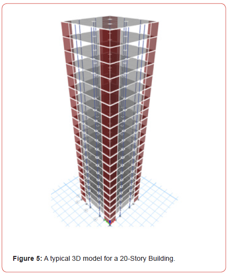
The 5 buildings that were compared differ in the number of stories (10, 20, 30, 40 and 50 stories). In order to maintain consistency in the structural properties of the building and reduce the number of variables to consider in the study and be consistent in terms of the building height and shear wall stiffness, the magnitude of the building plan area to building height ratio (A/H) was kept constant; also, the story stiffness related to (A/H) was kept constant. In this way, the lateral stiffness and the geometry of the buildings will remain consistent and will not be a factor in the variation of results. A typical model for a 20-story building is presented in Figure 5 (Figure 5).
Geometric properties
The chosen properties are typical to building structures. The
side of each building is taken to be the recommended overturning
minimum limit, H/5. The properties can be summarized as follows:
1. Floor’s geometry considered is square in shape and the floor
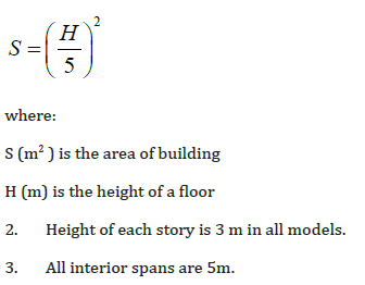
area is proportional to the building height as follow:
where:
S (m2 ) is the area of building
H (m) is the height of a floor
2. Height of each story is 3 m in all models.
3. All interior spans are 5m.
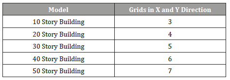
Number of grids in the X and Y direction are presented in Table
1 (Table 1).
Table 1:Number of grids in X and Y direction.
Structural properties
1. Shear walls have the same configuration in all models.
They are placed at the corners of the building and symmetric in the
X and Y direction.
2. Stiffness of shear walls in all models are accounted for by
an empirical formula as follow:
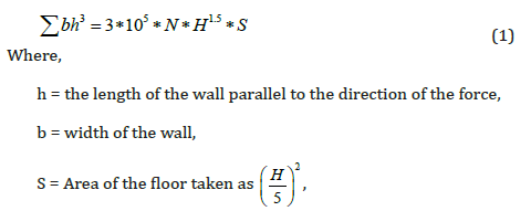
N = Number of stories in a building.
3. Area of columns were calculated using the following
relation:
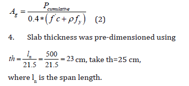
5. For each 5 stories going up, the dimension of the columns is reduced according to equation (2); also, the dimensions of the shear walls were reduced according to equation (1) with a thickness lower limit of 0.35m.
Static and dynamic loads
Static Loads were calculated according to the following:
Dead Load (KN/m2) =2.4*thickness = 6 KN/m2
Super-imposed Dead load = 3 KN/ m2
Live load=2 KN/ m2
For the dynamic load, all the buildings were all subjected to sinusoidal ground acceleration with a magnitude of 0.25 m/s2.
The periods of excitation depend on the structural system where the sloshing period of the TLD was tuned to be equal to the fundamental period of the structure.
Case study analysis
The model of the 20-story building will be taken as reference in order to illustrate the research setup and procedures. All other models were studied in the same conceptual way and the results are summarized in the following sections.
The buildings were modeled and analyzed using Etabs 2018. The objective was to calculate the base Shear, story drift and displacement under the most critical acceleration. A moderate seismic risk was used with a ground acceleration of 0.25g.
Modal analysis
The fundamental period was determined from the modal analysis, and the dynamic ground acceleration was assigned a period equal to the fundamental period of the structure. The response of the structure is then obtained at resonance. Table 2 summarizes the fundamental period of each model (Table 2).
Analysis of results
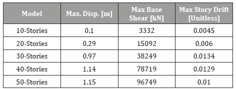
For the fundamental period obtained for the twenty-story model (1.808s), a time history sine function was defined having the same period and was assigned an acceleration of magnitude 0.25g. Table 3 shows the maximum values of the displacement, base shear and the story drift for each model without the installation of TLDs. Note that according to ASCE 7-10, Table 3, the inelastic drift limitation is 0.02ℎ𝛿𝑥 (Table 3).
Table 2:Fundamental period for each Model.
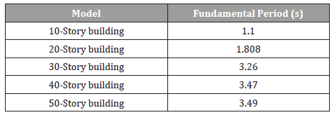
Table 3:Maximum Displacement, Base Shear and story drift at Resonance (without TLDs).
Solution
Solution definition
In designing a Passive Tuned Liquid Damper or TLD to control the lateral movement, the objective is to design a water tank with a specific water height to length ratio tuned to a specific sloshing frequency in order to effectively work out of phase with the structure. Several researchers considered various methods to evaluate tuned liquid dampers’ behavior. For example, the lumped mass method along with the linear wave theory suggested by [1]. In this research, the lumped mass method originally suggested by Housner [11], used by ACI 350.3 and organized by Khouri et al. [16], will be adopted. The water tank walls are assumed rigid. Hydrodynamic pressure induced by the liquid slosh is considered distinctively as impulsive pressure; this pressure is linearly related to the tank’s acceleration but in opposite direction. The sloshing pressure is a function of the acceleration of the tank and the sloshing frequency.
Procedure
For the assumed dynamic model of Figure 6, the interest is to calculate the height and weight of the convective (Wc) and impulsive (Wi) masses, and then the stiffness of the spring to which the convective mass is attached. The stiffness of the walls is infinite given that the walls are assumed rigid (Figure 6).
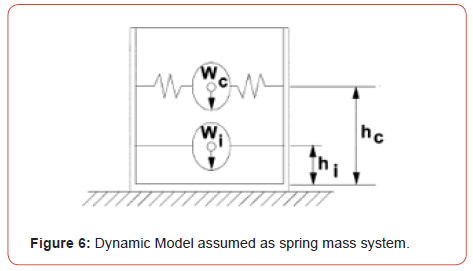
Equivalent weights of accelerating liquid
The ratios of the impulsive and the convective weights to the liquid weight are defined in equations (3) and (4) respectively, as follows:
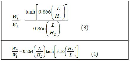
Where,
Wi = Equivalent weight of the impulsive component of the
stored liquid, (kN),
WC = Equivalent weight of the convective component of the
stored liquid, lb (kN),
WL = Total weight of the liquid, lb (kN), and
HL = Design depth of stored liquid, (m).
Height to centers of gravity excluding base pressure (EBP)
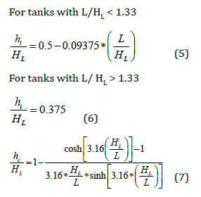
hc = height in meters above the base of the wall to the center of gravity of the convective lateral force for the case excluding base pressure (EBP), and
hi = height in meters above the base of the wall to the center of gravity of the impulsive lateral force for the case including base pressure (IBP).
Dynamic properties
The structural stiffness is computed based on the boundary
conditions.
For the Impulsive Component,
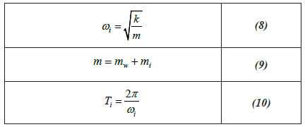
Where,
ωi= frequency of the impulsive mode of vibration, radian/s,
Ti = fundamental period of oscillation of the tank (plus the
impulsive component of the contents),
mi = impulsive mass of contained liquid per unit width of a
rectangular tank wall, (kg per meter of wall width), and
mi = mass per unit width of a rectangular tank wall, (kg per
meter of wall width).
For the Convective Component,
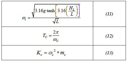
ωc= frequency of oscillation of the first (convective) mode of sloshing, radian/s, Tc = natural period of the first (convective) mode of sloshing, s, and Kc = spring constant attached to convective mass (kN/m).
For the 20-story building model, the fundamental period of the structure is 1.808s. Solving for “HL” when Tc=1.808s, and H/L=0.1, the required length L for the water tank and height of water HL is 0.77m and 0.077m, respectively. The stiffness of the spring to which the convective mass is attached is 0.47 kN/m.
Proposed model
The dynamic model, originally proposed by Housner and illustrated in Figure 3, is implemented in Etabs18 by simulating the springs as linear links. Point Masses were linked to the tank walls to simulate the convective and impulsive masses. In addition, another variable is considered; it is the mass of the water tank “MTLD” which is accounted for as a percentage of the building’s mass “% m”. Thus, the number of TLDs is calculated in terms of the percentage of “MTLD”. In order to account for the number of TLDs on ETABS, a model was implemented where the set, of all TLDs, is modeled as a single equivalent spring mass system (Figures 7 & 8).


Figure 7 and Figure 8 show the simulation of the spring mass system for the convective and the impulsive components on Etabs. Springs are fixed in the Y-Z direction for the convective component and fixed in all directions for the impulsive component.
If “Nt” is the number of TLDs required for a given model, the equivalent spring stiffness “Kequ”, equivalent convective mass “Mcequ” and equivalent impulsive mass “Miequ” are obtained as follow:
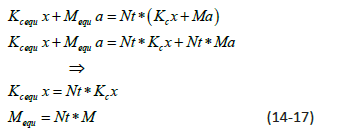
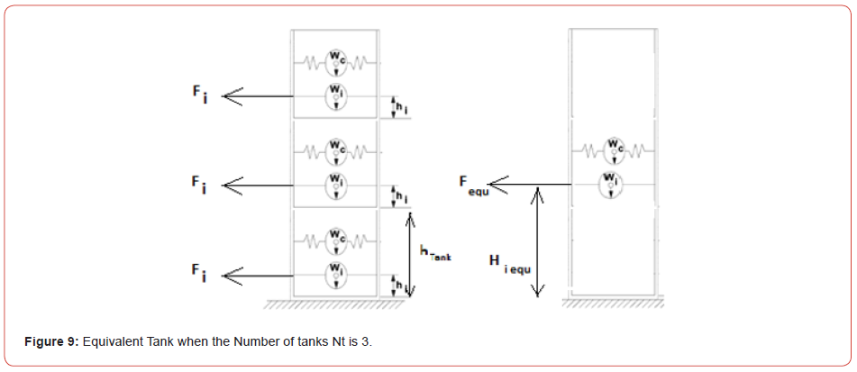
When the number of TLDs is large enough that it cannot fit in the floor area, several layers of TLDs are stacked on top of each other. Thus, the equivalent center of gravity heights of the impulsive and convective masses, hi equ and hcequ, are calculated in equations (18) and (19) respectively as follow:

(Figure 9) Figure 9 illustrates the equivalent TLD introduced in Etabs to account for n=3 layers of TLDs. The equivalent height of the convective and impulsive mass is calculated in terms of the height of the resultant force caused by the back-and-forth movement of the convective and impulsive mass.
Results & Analysis
The presented results show reductions in the displacement and
story drift; they are functions of “HL/L “, %m and the number of
stories.
The work procedure that yielded the results and the
configurations of the tuned liquid dampers are presented in the
following paragraphs.
Work procedure
The work proceeds as follows:
a. Modal analysis in free vibration is performed to obtain the
fundamental period T of the building.
b. Design the dimensions of TLDs for Tc = T and impose a
ratio HL/L. TLDs were designed for HL/L = 0.1, 0.2 and 0.3.
c. Load the structure with a sinusoidal acceleration having
a period equal to the fundamental period of the structure and
amplitude of 0.25g.
d. The imposed mass of the TLDs (MTLD), is used to compute
the number of TLDs required for each of the imposed ratio HL/L.
Also, the number of TLDs were computed for %m = 1%, 2%, 3%
and 4% of the buildings mass.
e. After setting up the TLDs within the building model,
displacement at the top story, base shear and maximum story drift
are recorded; process is repeated for the rest of the models.
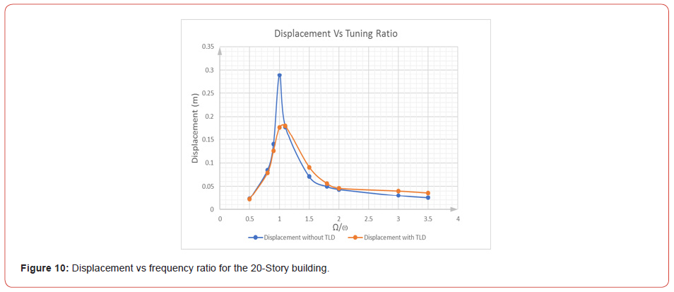
Figure 10 shows the displacement versus the frequency ratio
for the 20-story building. TLDs are most effective when tuned to
a frequency equal to the fundamental frequency of the building
(Figure 10).
Tuned liquid dampers configuration
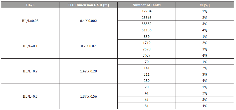
Table 4 presents the dimensions along with the number of water tanks for the 20-story building having different depth ratios HL/L and mass ratios %m. As mentioned earlier, TLDs are placed symmetrically such that the resultant force of the convective mass aligns with the center of rigidity of the floor (Table 4).
Table 4:TLDs numbers and dimensions for 20 story building.
Displacement after installation of TLD
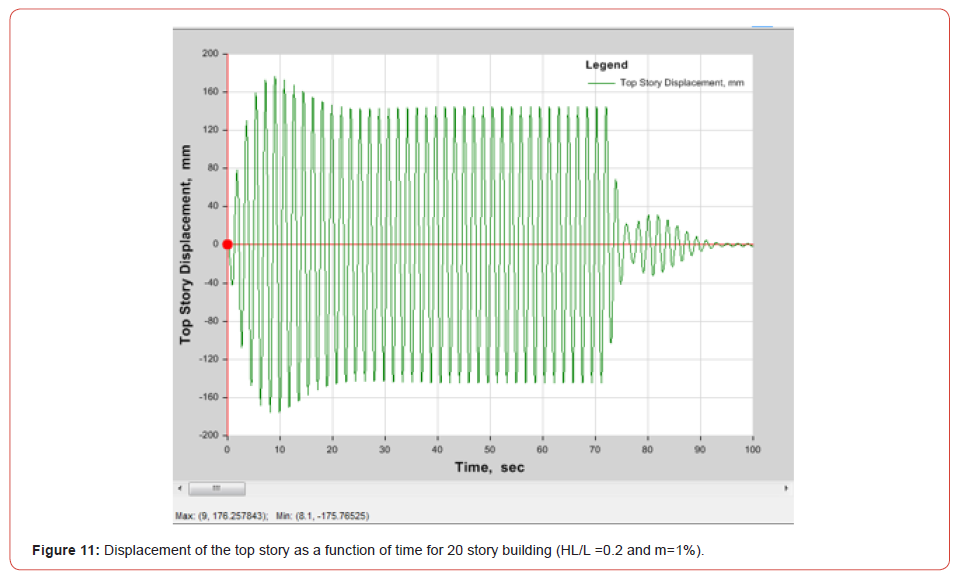
After installing the TLDs, Figure 11 shows the displacement
results extracted from ETABS at the top story of the 20-story
building for HL/L=0.2 and %m =1%. The displacement reductions
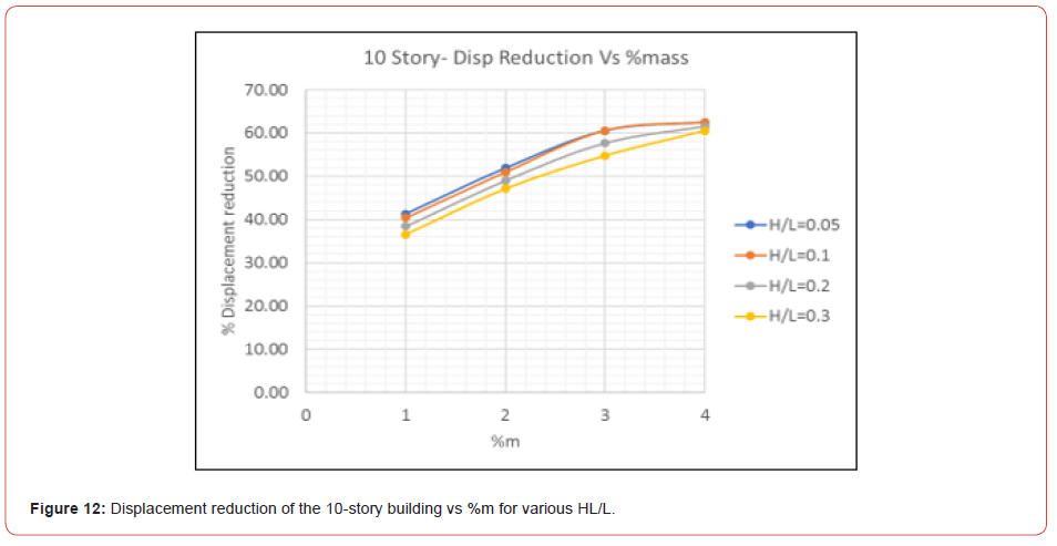
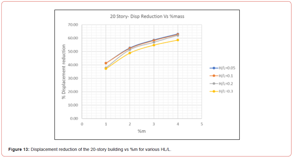
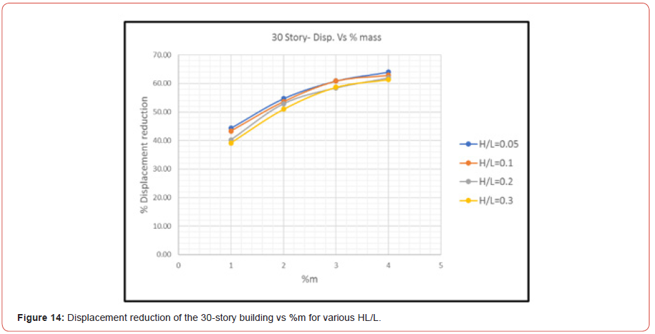
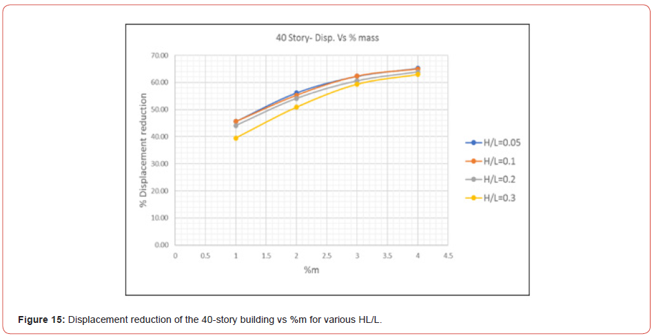
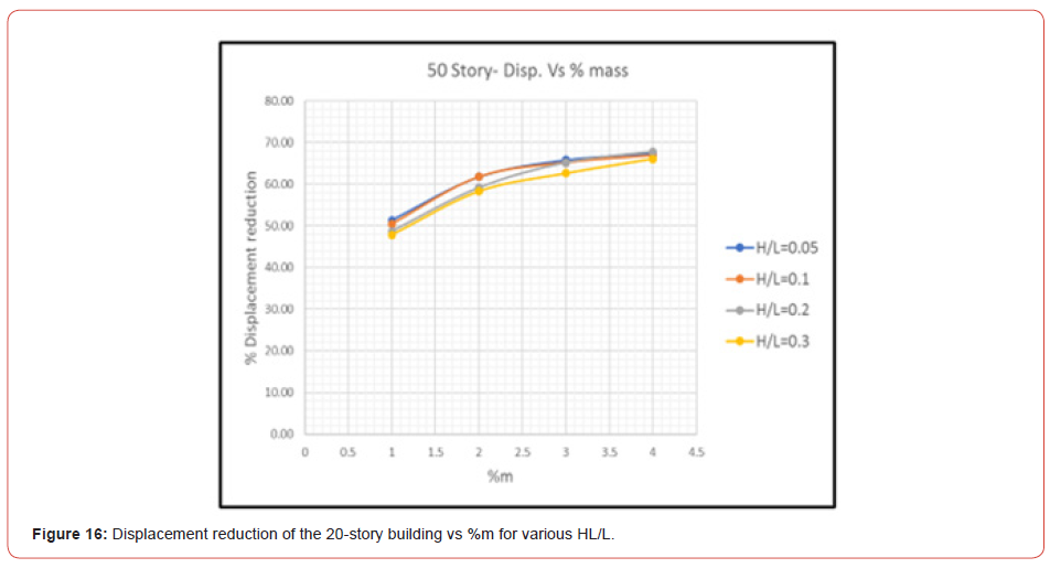
versus %m for different HL/L ratios are shown in Figure 12 to
Figure 16 (Figures 11-16) (Table 5).
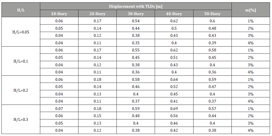
Table 5 shows the max displacement of each model for different
height to length ratios of TLDs.
Table 5:Max. Displacement [m] after installing TLDs for various Building heights and various H/L; Table also shows the corresponding %mass.
Story drift after installing TLDs
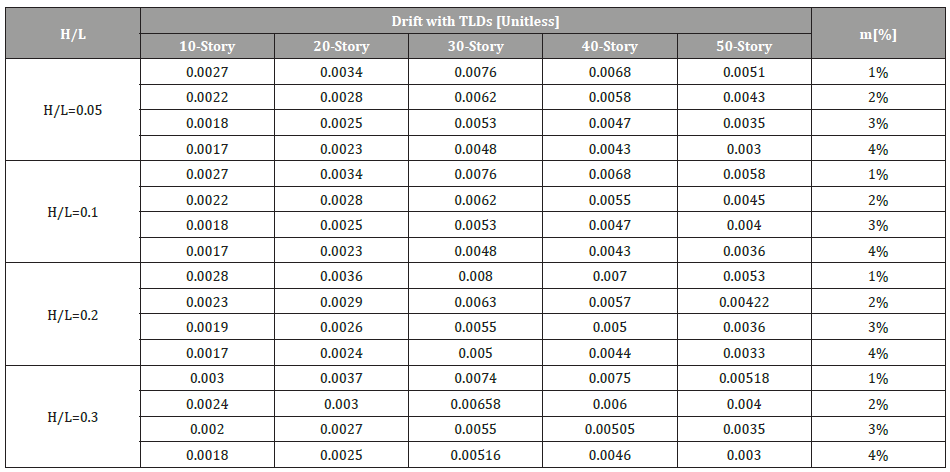
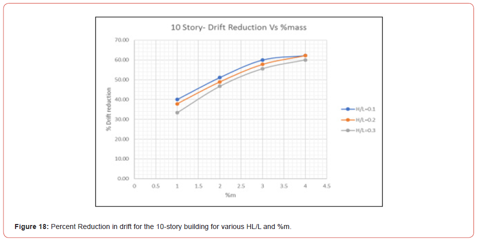
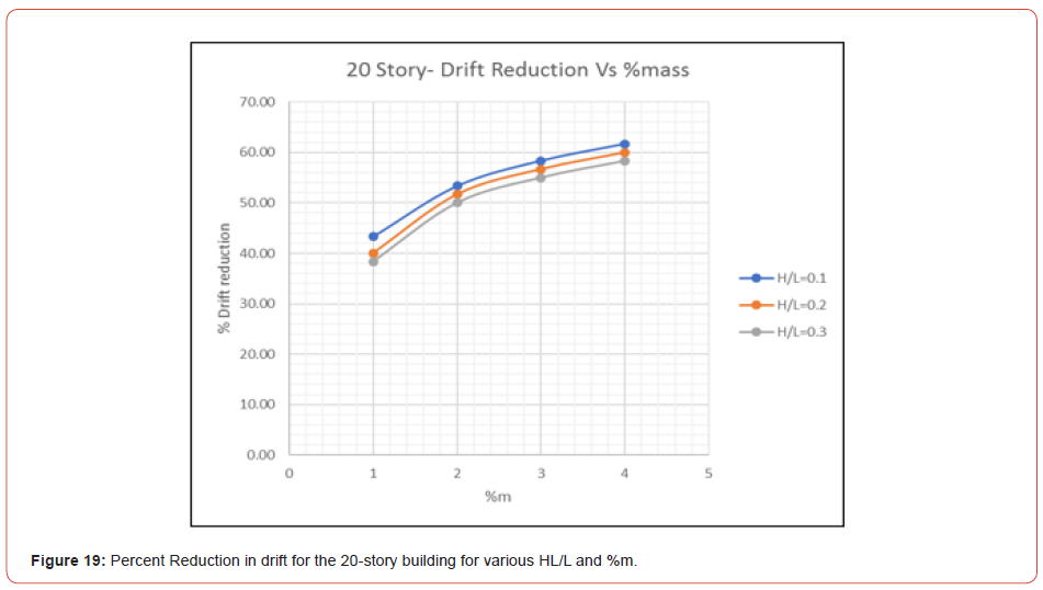
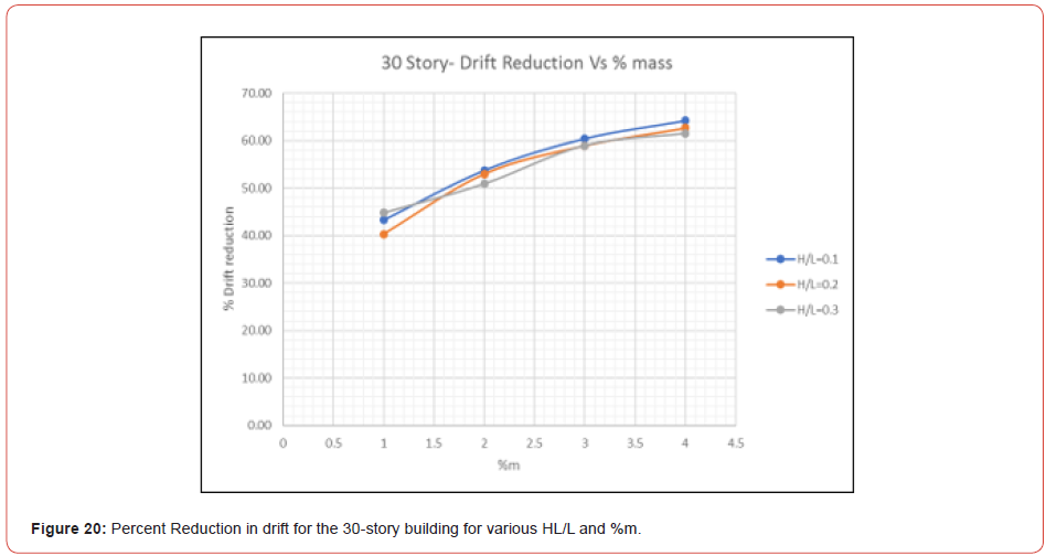
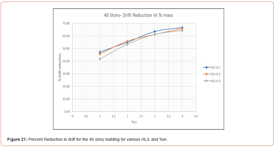
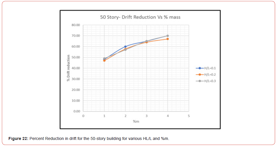
Figure 17 shows the story drift obtained from ETABS after the installation of TLDs with HL/L=0.2 and %m =1. The story drift is the differential displacement of two consecutive stories divided by the height of the story. The maximum story drift for the remaining models is presented in Figure 18 to Figure 22 (Figures 17-22). Also, Table 6 shows the max elastic story drift of each model for various HL/L of TLDs (Table 6).
Table 6:Maximum elastic story drift with TLDs for all models with various HL/L ratios and various Building heights; Table also shows the corresponding %mass.

Discussion of results
Starting with the frequency of the tuned liquid damper, a maximum response is obtained with a frequency ratio of about 1.06 when TLDs are installed. The small difference in response when the frequency ratio is 1 and 1.06 is due to damping effect; it shows that the optimum tuning frequency is not exactly equal to the fundamental frequency of the structure but slightly different

Concerning the displacement of the models, Figure 12 to Figure 16 show that the percentage of displacement reduction increases with the %m until the reduction becomes asymptotic; this means that a % m greater than 4% will not be feasible.
Moreover, results show that the depth ratio HL/L is inversely related to the convective and impulsive mass ratios; when HL/L increases the convective mass decreases, thus the effect of TLD is reduced. Also, as the depth ratio HL/L increases, the reduction in response decreases. In addition, for HL/L=0.005, the percentage of the displacement’s reduction is almost the same as for HL/L=0.1; this shows that the depth ratio has a lower limit under which TLDs will no longer be effective. Comparing the maximum displacement with the displacement limitations suggested by [3], results show that after installing TLDs, displacement are within limits.
Similarly for the story drift, the variation of reduction increases with %m, however it is decreasing when HL/L increases. Referring to Table 3, the elastic story drift for the 30, 40 and 50 story building before installation of TLDs was 0.0134, 0.0129 and 0.01, respectively. These values for story drift are not acceptable as per the ASCE limitations. The inelastic story drift limitation is 0.02; in other words, while performing an elastic analysis using the finite element method, elastic story drift computed should not exceed

According to the results summarized in Table 6, the best choice of TLD to reduce the story drift for the 30-story building is for HL/ L=0,1 and %m = 4. Whereas for the 40 and 50 story buildings, there are options to select from: HL/L=0.1, HL/L=0.2 or HL/L=0.3, as long as the story drift is smaller than 0.005 for some %m. Finally, for both, the displacement and story drift, the % reduction of the response increased with the number of stories.
Table 7:Assigned Frequency for the models.
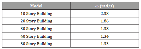
In order to make use of the computed results, equations are generated to allow the calculation of the reduction of displacement and story drift for models with similar structural properties that are subjected to certain acceleration. Thus, a value for is assigned to each model and summarized in Table 7, where K (kN/m) and M (kg) represent the stiffness and mass of the building, respectively (Table 7).
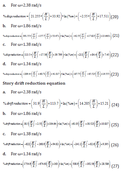
An exponential trend-line was determined for each displacement curve and story drift versus %m in order to obtain one equation that is a function of HL/L and %m from which we can calculate the reduction of the displacement as well as the drift for a given H/L and %m.
Displacement reduction Equation
Regressions equations for the % displacement reduction as a function of H/L and %m for various values of ω are presented in equations (20) to 27 as follows:
Design Procedure
The following steps can apply in the process of designing TLDs
for building structures under the similar conditions evaluated in
this study.
a. Compute the maximum story drift and displacement of the
building without dampers.
b. Compute the building stiffness and mass, and then calculate
K/M.
c. Determine the reduction of the displacement or drift for the
building to comply with Code’s limitations in selecting of HL/L
and % m. Starting with HL/L=0.1 is recommended.
d. From equations 21 to 27, choose the corresponding equation
as a function of K/M and the response reduction that is in
question.
e. If the reduction of HL/L and % m is not enough to comply with
code limitations, the % m is to be increased.
f. Once the depth ratio “HL/L” and mass ratio “%m” are sufficient,
apply the corresponding equations 3 to 13 to calculate the
corresponding structural properties to be used in the design/
construction process.
Conclusion
In this Study, five shear wall buildings were analyzed in Etabs18 under a Time History function. The objective was to evaluate the use of TLDs to reduce displacements in building structures. A modal analysis was performed to find the natural period of each model. The period assigned to the time history function was the same as the natural period of the building to get the most critical displacement and story drift of the structure. Liquid Dampers were tuned for each model by considering the spring mass model provided by Housner and implemented on Etabs18. In this study, TLDs were studied for 4 depth ratios HL/L (0.05, 0.1, 0.2 and 0.3). Analysis showed that tuned liquid dampers can be used to reduce the response of a structure when subjected to dynamic loadings. A reduction in the response by as much as 40% - 65% is obtained when the forcing frequency matches the building’s natural frequency. In other words, the use of TLDs is most effective in reducing the building’s response when TLDs are tuned to the natural period of the structure, and the damping effect of a tuned liquid damper is more effective for high rise buildings. The mass ratio (% m) of the TLDs, increases the reduction of displacement and story drift response of the building, however it should be carefully chosen.
Finally, reduction of displacement and story drift were provided as formulas in function of the depth ratio “ HL/L “ and the mass ratio “%m.” Engineers and designers can use this suggested design procedure to design TLDs for building structures.
Acknowledgment
The authors thank Engineer Wassim Elias for his contribution to this work. Also, thanks to Optimal Engineering Consulting and Contracting, (OECC) for sponsoring part of this work, and thanks to the Lebanese University, Faculty of Engineering for sponsoring the other part of this on-going research.
Conflict of Interest
No conflict of interest.
References
- T Novo, H Varum, F Teixeira-Dias, H Rodrigues, M Falcao Silva, et al. (2013) Tuned liquid dampers simulation for earthquake response control of buildings. Bulleting of Earthquake Engineering.
- KD Shashikant (2013) Earthquake‐Resistant Design of Structure, Oxford University Press.
- M Khouri, W Elias (2014) On the General Evaluation of Allowable Maximum Drift at the top of Shear Walls (Constant and Variable Stiffness). International Journal of Civil Engineering and Construction Science, 1(2): 18-25.
- M Khouri, E El-Haber (2017) An Innovative Technique to Reduce the Lateral Displacement of Building Structures Using Springs. Journal of Mechanical and Civil Engineering, 14(3): 51-57.
- V Rao K (2013) Experimental and Numerical Studies On tuned liquid dampers, ethesis.nitrkl.ac.in/4938/1/211CE2023.
- Y Tamura, K Fuji (1995) Effectiveness of Tuned Liquid Dampers under wind excitation, Engineering Structures, pp. 609-621.
- R Anuja, Z Zill, G Aparna, B Biswajit (2019) On the nonlinear performance of a tuned sloshing damper under small amplitude excitation. Vibration and Control, pp. 1-11.
- Kareem, W Sun (1987) Stochastic Response of Structures with Fluid-Containing Appendages, Sound and Vibration, pp. 389-408.
- SM Falcão, C Costa (2008) Experimental studies on the characteristics of tuned liquid dampers, in 14th World conference on earthquake engineering.
- SK Bhattacharyya (2016) Tuned Sloshing Damper in Response Control of Tall Building Structure, Proc Indian Natn Sci Acad.
- GW Housner (1963) The Dynamic Behavior of Water Tanks, vol. 53.
- J Krabbenhoft (2011) Shallow Water Tuned Liquid Dampers: Modeling, simulation and experiments. Technical University of Denmark.
- K Fujii, Y Tamura, T Sato, T Wakahara (1990) Wind-induced vibration of tower and practical applications of Tuned Sloshing Damper. Journal of Wind Engineering and Industrial Aerodynamics, pp. 263-272.
- AC institute, Seismic Design of Liquid-Containing Concrete Structures and Commentary, in American Concrete institute 350: 3-6.
- R Aakash (2018) Analysis of Tuned Liquid Damper (TLD) in Controlling Earthquake Response of a Building using Sap2000. International Research Journal of Engineering and Technology (IRJET) 05: 79-95.
- M Khouri, W Elias (2015) Determination of Hydrodynamic Forces in Rectangular Storage Tanks, International Journal of Scientific Research and Reviews, 4(1): 50-67.
- T Wakahara, T Ohyama, K Fuji (1992) Suppression of Wind-Induced Vibration of a Tall Building using Tuned Liquid Dampers. Journal of Wind Engineering and Industrial Aerodynamics, pp. 41-44.
- ACI (2011) Building Code Requirements for Structural Concrete (ACI 318M-11).
- M Khouri, W Elias (2012) On the Evaluation of Hydrodynamic Forces in Shallow Storage Circular Tanks due to Seismic Actions, International Journal of Advances and Trends in Engineering Materials and their Applications, 1(1): 73-80.
-
Charles Maroun Khadige, Michel Farid Khouri. Controlling the Lateral Drift Using Hydraulic Systems. Cur Trends Civil & Struct Eng. 9(1): 2022. CTCSE.MS.ID.000702. DOI: 10.33552/CTCSE.2022.09.000702.
-
Creep, Polymer materials, Mechanical state equation, Complex modes of loading, Experimental test
-

This work is licensed under a Creative Commons Attribution-NonCommercial 4.0 International License.


