 Research Article
Assessment of the Theoretical Methods to Estimate the Tension Load Capacity of CFA Piles
Rami M Bakr, Department of Civil engineering, Faculty of Engineering, Delta University for Science and Technology, Gamasa, Egypt.
Received Date: November 15, 2019; Published Date: November 22, 2019
Abstract
This paper studies the behavior of three continuous flight auger piles executed in unsaturated soil subjected to tension forces. Field tests and laboratory tests were conducted on representative samples collected from a borehole 17m deep. The water table does not exist until a depth of 17m. The author carried out slow static load tests to check the behavior of the piles when subjected to tension forces. The tension capacity of these piles was also investigated using theoretical methods and semi-empirical approaches. The author compared the values estimated from the theoretical and semi-empirical methods considered with those obtained using field load tests. One of the tested piles was loaded until removal from the soil to investigate its geometry. The results showed that the theoretical methods give higher values compared with static load tests, while semi-empirical methods give low estimates.
Keywords: Tension piles; Flight auger; Field tests
Introduction
Recently, the use of continuous flight auger piles has significantly increased. Higher productivity and greater capacity to transfer larger loads to the subsoil. The Continuous Flight Auger (CFA) pile, installed using a continuous helix auger, was first used in the United States during the fifties and in the seventies in Europe. In Egypt, the use of this type of piling has become more prevalent, especially in the Delta region. One of the factors that led to the spread of this type of piles is its suitability for the soil in the delta region, where the topsoil is mostly medium to stiff clay, followed by sandy soil. Since the use of this pile is increasing, it becomes imperative to understand its behavior.
Historical review
Since the beginning of the invention of CFA piles so far there has been a significant development in technology, and presently they can be installed up to 32m deep, 1200mm in diameter, and torque of up to 390 kN.m. CFA piles became very widespread due to their technical advantages combined with relatively low cost [1]. However, these authors warn from the adverse effects during the production process, which may need special attention, especially with pile continuity, soil disturbance due to auger extraction, and failure in weak soils due to high applied pressures causing a sig nificant waste of concrete. Operator skills play an essential role in controlling the construction of CFA piles is the most severe limitation of these piles [2]. The pilling contractor must take all necessary precautions during the installation process, including excavation, auger extraction, and positioning the reinforcements.
Advantages
Continuous flight auger piles are usually installed in most soil conditions. In addition to their efficiency to resist all types of loads including compressive, uplift, and lateral loads, they are also cost-efficient foundation solution. They can be installed up to depths of 32m and diameters of 300 mm to 1000mm, low noise level and no vibration and low noise level so ideal in built-up areas with weak soil conditions and high levels of groundwater, compared to bored piles, construction is rapid as temporary casings or support systems are not needed, and eliminates the soil relaxation. Marchetti dilatometer was used before and after installing a pile to investigate this effect. It was noted that the CFA piling construction method did not cause this relaxation. Bottiau [2] emphasizes that another critical advantage of the CFA pile is the possibility of continuous monitoring, which furnishes documentation on the piles installation.
Tension capacity of piles
The tension capacity of piles depends on several factors; these are construction methods, properties of the pile, and properties of soil. The design of piles to resist tension forces is widespread in the construction field. There are many situations in which this type of structures is mandatory, for example, foundations of power transmission towers, foundations that cross over extensive soils, foundations of lighting poles subjected to lateral wind forces. There are many theoretical methods to estimate the tension capacity for piles. However, the use of these methods is minimal because the parameters involved with these methods are complicated to obtain. Besides, these methods also may present a very optimistic and very conservative tension capacity. In Egypt, estimating tension capacity for piles using semi-empirical methods developed for compressive forces is a common practice among foundation engineers. In these cases, the tension capacity may be assumed as a percentage of the total skin friction resistance of the pile under compressive loading conditions. There are many methods to obtain the tension capacity of a pile. These methods are described by other researchers, such as [3,4].
Field Tests
Field tests, such as SPT, and refraction were performed.
Laboratory Tests
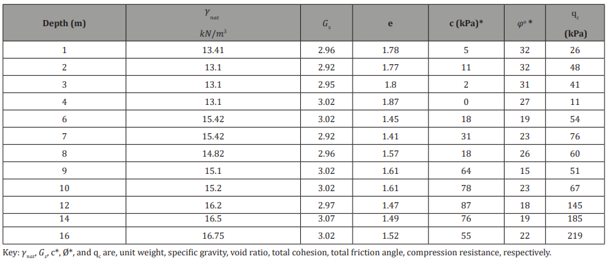
Laboratory tests were conducted out to determine the soil properties, on disturbed samples, and undisturbed samples, including; triaxial, unconfined compression, odometer, permeability tests, etc. Static and Dynamic Load tests also performed. The subsoil comprises of a superficial layer approximately 6.5m thick, composed of high porosity silty-sand clay, followed by clayey-sandy silt to a depth of 19m; the water table encountered at depth 17m. The upper layer is collapsible, presenting collapse ratios ranging from 2.4% to 24%, depending on the applied pressure, according to Vargas [10]. Some geotechnical characteristics of the experimental area presented in the following tables (Table 1 & 2).
Table 1: Average results of the field tests.

Table 2: Average geotechnical parameters obtained by laboratory tests.
Test Piles and Loading System
Three Continuous Flight Auger piles constructed in the study area. The CFA pile has the following dimensions: nominal diameter 0.40m and length 12m. The piles followed a predefined alignment and spacing between them was 4.80m. Three pile caps were constructed with dimensions of 0.70 x 0.70 x 0.70 𝑚3 for each pile studied. A concrete with strength, fcu= 25MPa, was used in the pile cap. Vertical steel reinforcement of 5Ø 16mm, 6m in length, was used.
Static Load Tests
For each pile, a static load test was carried out with a maintained load method. The static load tests were carried out ASTM guidelines. The test load was applied in steps of 120kN, up to the load at which the displacements indicated a rupture of the pile. Unloading was performed in four stages.
Estimation of the Tension Capacity
The tension capacity of the piles included in this study was estimated using theoretical methods. These are [6,7], and the method of the University of Grenoble, based on Martin [6] Semi-empirical methods were also used to estimate the lateral resistance as a percent of compression forces. The following methods studied were used; Décourt & Quaresma [3], Aoki & Velloso [9] and Antunes& Cabral [10]. The results of the theoretical analysis were compared to those obtained using the load tests.
Results of Load Tests
The load vs. settlement curves for all cases are shown in Figure 1. The magnitudes of the ultimate load and corresponding maximum displacement for each pile are presented in Table 3 (Figure 1), (Table 3,4).
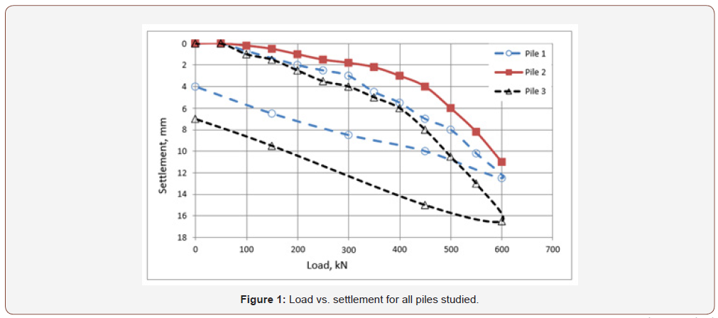
Table 3: Average geotechnical parameters obtained by laboratory tests.

Table 3: Ultimate loads and corresponding displacements reached in the loading tests.

Table 4: Estimated ultimate loads by Van der Veen´s Method [5].

Lateral Capacity Estimated by Semi-Empirical Methods
Table 5: Lateral resistance estimated using the studied methods.
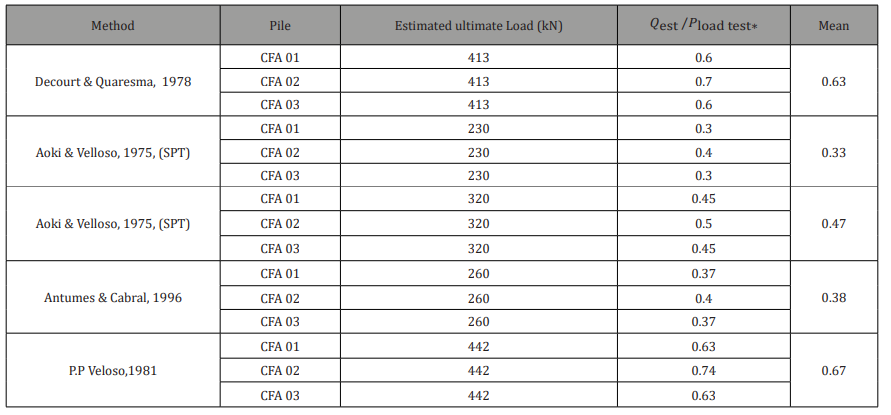
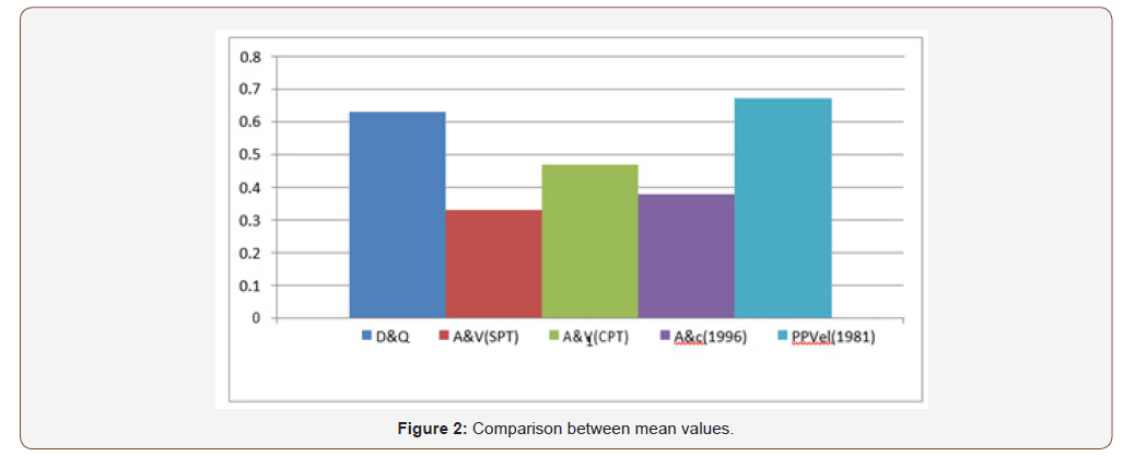
The lateral resistance estimated by semiempirical methods is presented in Table 5. A comparison between the mean values obtained of 𝑄est /𝑃load, determined by each semiempirical method considered, is presented in Figure 2 (Table 5)(Figure 2).
Mean values of 𝑄est /𝑃load* test obtained by each semi-empirical method considered. Figure 2 presents the method of PP Velloso [9] the mean value of 𝑄est /𝑃load test* closest to unity compared with other methods. The purpose of Aoki & Velloso (SPT) gave the most conservative value of 𝑄est /𝑃load test* of all the methods studied. All methods give lower values than those obtained from load tests.
Tension Capacity Estimated by Theoretical Methods
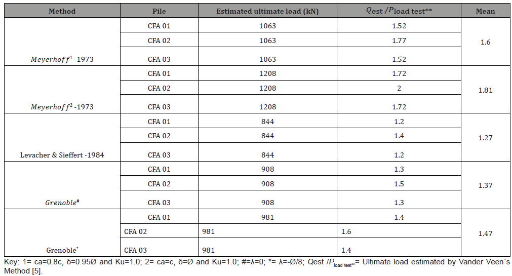
The estimated tension load capacity using the theoretical methods studied are presented in Table 6. The comparison between the mean 𝑄est /𝑃load test** values obtained, as determined by each theoretical method considered, is shown in Figure 3 (Table 6) (Figure 3).
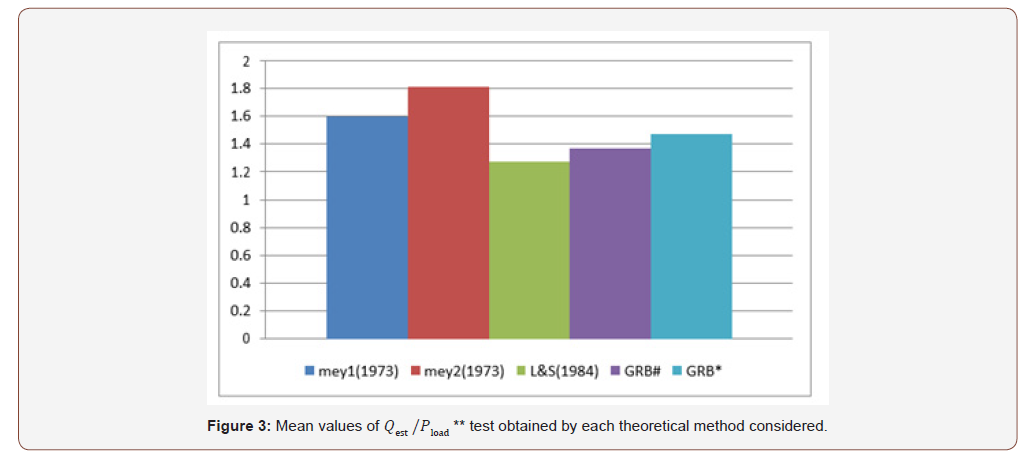
Table 6: Tension capacity by the studied methods.
According to Figure 3, the method of Levacher & Sieffert [7] gave the mean value of Pest /𝑃load test** closest to unity with respect to other theoretical methods. The method of Meyerhoff [6], for ca=c, δ=Ø, presented the mean 𝑄est /𝑃load test** value, which was furthest from unity. All the theoretical methods employed presented 𝑄est /𝑃load test** values, on average, at least 27% higher than the measured values obtained in the load tests.
Removal of the Pile
After performing the load tests, one pile was removed to investigate its geometric characteristics. Several attempts were made to make the removal viable. The procedure of pile removal is described as follows:
1. Removal of the pile head block
2. Device to fix the hoist: A metallic ring was manufactured to be used in the pullout process. The ring was divided into two parts performed and then fixed around the head of the pile. The gap between pile and ring was filled with cement slurry, to assure tanginess of the bonding between them.
3. Pile removal: Thirty days after the ring was fixed, pile removal was performed. For this, it was necessary to excavate around its shaft manually. An appropriate hoist was used during the pullout process to assure the verticality of the pile since it should lift the pile to a level of at least 1 m above the ground.
4. Post-extraction analysis of the pile: A comprehensive investigation of the pile was then performed, revealing essential data of the geometry of the shaft surface and the pile toe.
• Shaft surface somehow was slightly wavy due to the drill along the shaft.
• A survey of the pile perimeter was conducted and thus to get the average diameter. the pile diameter was enlarged at depth from 1.5 to 3.0m.
• The shaft perimeter was also determined, thus obtaining its average diameter; it was verified that the actual diameter (40.4cm) was on average 1% greater than the nominal diameter (40cm).
Conclusion
The following conclusions may be extracted from this research:
1. The semi-empirical methods used in this research give tension capacity lower values compared with results obtained from the load tests. The process with the closest benefits got average values of 67% of the values obtained in the load tests.
2. The theoretical methods used in the estimation of tension capacity give higher values than those obtained from the load tests.
3. The use of theoretical techniques depends on the adoption of parameters like ca, δ, Ø, etc. This situation, due to the lack of useful soil value data along the length of the pile shaft, may lead to the wrong estimation of tension capacity.
4. The helix auger may make the pile shaft crimpy. An increase in pile diameter was noted between 1.5m and 3m depths, due to the existence of weak soil at this depth.
Acknowledgement
None.
Conflicts of Interest
No conflict of interest.
References
- Brons KF, Kool AF (1988) Methods to improve the quality of auger piles. In: International Geotechnical Seminar on Deep Foundations on Bored Auger Piles, Ghent- Belgium. Proceedings Rotterdam: Balkema AA, 269-272.
- Bottiau M (1993) Pile walling with the PCS Method. In: IGSDFBAP Ghent-Belgium Proceedings. Rotterdam: Balkeman AA, pp.185-190.
- Carvalho D (1991) Analysis of tension loads of instrumented excavated piles built at the Experimental Field of Danziger, FAB 1983. The load capacity of foundations submitted to vertical tension forces. (Dissertation) Federal University of Rio de Janeiro, Brazil, pp.331.
- Nogueira RCR (2008) Behavior of root piles submitted to tension loads performed in diabasic soil, typical of the region of Campinas, Brazil. In: Congresso Luso-Brasileiro de Geotecnia, Porto. Portugal.
- Vander Veen C (1953) The bearing capacity of a pile. In: Procedures of Third International Conference of Soil Mechanics and Foundation Engineering 2: 84-90.
- Meyerhoff GG (1973) The tension capacity of foundations underoblique loads. Canadian Geotechnical Journal 10: 64-70.
- Levasher DR, Sieffert JG (1984) Tests on model tension piles. Journal of Geotechnical Engineering. ASCE 110(12): 1735-1747.
- Décourt L, Quaresma AR (1978) Capacidade de carga de estacas a partir de valores de SPT. In: Brazilian Congress of Soil Mechanics and Foundation Engineering, Rio de Janeiro- Brazil. Proceedings São Paulo: ABMS, pp.367-376.
- Proceedings São Paulo: ABMS (1996) 2: 105-109.
- Antunes WR, Cabral DA (1996) The load capacity of continuous flight auger pile. In: Seminar of Engineering of Special Foundations. São Paulo-Brazil.
-
Rami M Bakr. Assessment of the Theoretical Methods to Estimate the Tension Load Capacity of CFA Piles. Cur Trends Civil & Struct Eng. 4(3): 2019. CTCSE.MS.ID.000587.
-
Tension piles, Flight auger, Field tests, Construction, Design of piles, Dynamic load, Silty-sand clay
-

This work is licensed under a Creative Commons Attribution-NonCommercial 4.0 International License.
- Abstract
- Introduction
- Field Tests
- Laboratory Tests
- Test Piles and Loading System
- Static Load Tests
- Estimation of the Tension Capacity
- Results of Load Tests
- Lateral Capacity Estimated by Semi-Empirical Methods
- Tension Capacity Estimated by Theoretical Methods
- Removal of the Pile
- Conclusion
- Acknowledgement
- Conflicts of Interest
- References


