 Research Article
Studying and Investigating the Effect of Soil Porosity on the Dynamic Behavior of Reinforced Concrete Piles under Explosive Load
Seyed Ali Mousavi Davoudi*
Graduated with a Master’s Degree, Department of Structural Engineering, Faculty of Civil Engineering, Tabari Higher Education Center, Iran
Seyed Ali Mousavi Davoudi, Graduated with a Master’s Degree, Department of Structural Engineering, Faculty of Civil Engineering, Tabari Higher Education Center, Iran
Received Date:December 08, 2024; Published Date:January 09, 2024
Abstract
In recent years, the use of piles under important structures such as power plant equipment, petrochemical complexes, marine structures, and bridges has expanded greatly, and the safe and economical design of these types of foundations under the effect of dynamic loads is of particular importance. Paying attention to the fact that pile and soil interaction along with the effects caused by seismic forces is considered as an important issue in the analysis of foundations. Therefore, obtaining accurate and close to reality answers from the behavior of concrete pile under the application of these forces and dynamic analysis of the pile is important for seismic designs. Until now, various methods such as: Winkler model method, finite element method, inseparable boundary method or boundary element method and integral equation method have been proposed to solve soil and pile interaction problems. In this research, in order to investigate the effect of soil porosity on improving the dynamic behavior of concrete piles, finite element analysis was used, for this purpose, according to dynamic methods, the numerical model will be able to calculate the effect of gravity and seismic load in analyzing the dynamic response of piles. . Also, the soil is considered as a continuous elastic medium and the concrete pile as an elastoplastic strip. Piles in soils with different porosities will be affected by seismic waves and incoming forces. Modeling is done in Abaqus software, and pile and soil will be studied as several different materials and with the effect of interaction on each other. At the end of this research, the results were observed, with the increase of soil porosity in granular and clay soils, the bearing capacity of the pile group will decrease, and it was also observed that the behavior of the pile group will change with the change of the dimension and dimensions of the pile group, and with the increase of the dimension of the pile group The bearing capacity of the pile also increases.
Keywords:Reinforced concrete pile; dynamic behavior; soil-structure interaction; soil porosity
Introduction
Piles are structural members made of wood, concrete, steel
or other materials that are used to transfer surface loads to lower
levels in the soil [1]. This transfer is done by distributing the load
along the body of the pile or directly transferring the load to the
lower layer through the tip of the pile, the first case is called a
friction pile and the second case is called a support pile [2]. Usually,
all piles transfer the load as a combination of body friction and tip
resistance, except for cases where, for example, the pile penetrates
a very soft soil to reach a hard bed. Candles are usually used for the
following purposes [3]:
a. Transferring the load of huge structures into the lower
layers. (vertical and lateral loads)
b. Resistance against upward traction or overturning, for
example, for uniform foundations under the water surface or
to keep bridge foundations against overturning caused by side
loads such as wind.
c. The density of soft and non-sticky layers by a combination
of displacements by the volume of the pile and the movement
of the pile in a vibrational way. These types of candles may be
pulled out later.
d. Settlement control, when there is a strip or wide footing
on the soil under which there is a layer with high density.
e. Hardening the soil under the foundation to control the
vibration range and natural frequency of the system.
f. As a more reliable factor for bridge bases or abutments
[4].
g. In offshore structures to transfer loads above the water
level to the ground below.
Sometimes to control ground movements (e.g. landslides). Piles may break under vertical and lateral loads. Also, in long members, buckling may occur. A pile foundation is much more expensive than a strip foundation and a wide foundation. In any case of foundation design, studies on local soil characteristics are very important. Because based on these studies, it should be carefully decided whether there is a need for candles and, if so, whether a greater number or length of candles is needed [5].
In recent years, the use of piles under important structures such as power plant equipment, petrochemical complexes, marine structures, and bridges has expanded greatly, so the failure and damage of such structures after an earthquake occurs due to lack of observation, various losses such as loss of life, economic, environmental, therefore, this issue makes the safe design of these types of foundations under the effect of lateral seismic loads to be of special importance and should be done during the service life of the piles, taking into account the effective factors [6]. In general, any structure that is buried in the soil is affected by the six components of the earth during an earthquake. These components include two lateral components, one vertical component and three torsional components around the coordinate axes. Accordingly, the structure and the soil around it have a reciprocal effect on each other and this factor causes more changes due to seismic waves. The meaning of this is that one should not only analyze the structure in seismic analysis and the effect of the interaction between the structure and the soil should be taken into consideration [7]. The behavior and seismic response of the soil-structure system when subjected to a dynamic loading is a function of the three factors of ground effect, forces and the desired system. The seismic behavior of the pile is not exempted from this rule, and for this reason, the seismic analysis of the pile, considering the effect of the interaction between the soil and the pile, requires earthquake risk analysis to a large extent, so that based on that, a correct assessment of the structure’s performance during an earthquake can be made. After that he did [7].
Jian Fei Luo et al. in 2011, in which the effect of the fixed axial load at the top of the pile on the permanent dynamic response of the pile is discussed, which shows that the fixed axial load, which is the mass of the pile, only affects the inertia of the pile. and through inertia it will affect the axial permanent dynamic response, but in the horizontal permanent dynamic response of the pile, both inertial and force factors will be involved separately. In general, this research has stated that increasing or decreasing the amount of static force on the top of the pile will have the same effect on the permanent dynamic response of the pile and shows that, when the modulus of elasticity, Rayleigh wave frequency and pile length are small, the effect of the static force The top of the pile will be greater on the permanent dynamic response of the pile. Also, based on the studies carried out in this research, the end of the pile 0.65 of the bedrock has been identified as the area of change in the behavior of the pile [8].
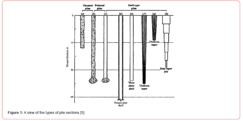
In 2009, Jianlian Zhu and his colleagues studied the transient response of the pile in saturated soil, which they studied, and in which the dynamic response of the pile and the saturated soil around it is expressed using Lagrange’s equation and finite element, which shows It gives for triangular and rectangular loads in 2 seconds (+1, -1), the maximum impact of the load on the transient dynamic response will be in the first second, i.e. the end of loading. This effect will be true for the dynamic response of both the pile and the saturated soil around the pile [9]. In a 2015 research, Zheng et al presented an analytical study on the vertical vibration of an elastic pile embedded in porous soil. The degraded soil is divided into two halves, which is under the base of the pile and a set of independent thin layers along its shaft. The dynamic interaction problem is proposed and solved by extending a method originally for a rigid foundation. The validity of the derived solution is verified by comparing with existing solutions. Mathematical examples have also been used to show the sensitivity of vertical pile impedance to the relative stiffness of two soil parts [10] (Figure 1).
Research Method
In this research, in order to investigate the effect of soil porosity on improving the dynamic behavior of reinforced concrete piles, four study samples named A, B, C, and D have been used, and these samples will be analyzed by Abacus finite element software. Figure 2 shows the characteristics of the tested groups and the effective parameters of these samples. In Table 1, general examples and effective parameters analyzed are presented.
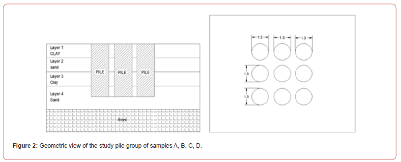
Table 1:General characteristics of the analyzed samples.

Soil mechanical characteristics
Table 2:Mechanical properties of clayey soil.

Table 3:Mechanical characteristics of granular soil.

In Tables 2 & 3 show the mechanical characteristics of the soil that will be used in the modeling of the sample.
Mechanical characteristics of rebars
In this research, the steel rebar is S400 type. To define the nonlinear mechanical behavior of steel rebars more easily, the stress-strain curve of steel is assumed to be bilinear. Therefore, it is enough to specify two slopes as the primary and secondary elasticity model and yield stress value. The specifications of S400 steel used in this modeling are shown in Tables 4-6.
Table 4:Mechanical characteristics of rebar.

Table 5:Mechanical linear isotropic characteristics of steel..

Table 6:Mechanical bilinear isotropic characteristics of steel.

Mechanical properties of concrete
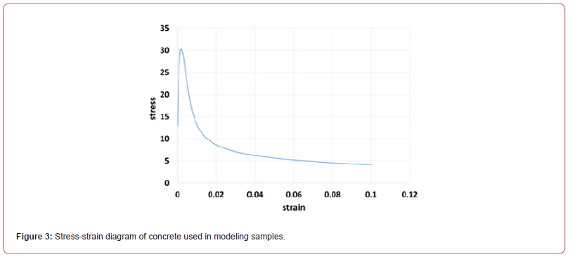
To define concrete in Abaqus finite element software, there is a behavior model called concrete damage plasticity model. This model has the general ability to model the behavior of concrete or any other material with semi-brittle behavior. This model uses the concept of isotropic failure in the elastic range along with the compressive behavior in the plastic range to model the inelastic behavior of concrete. In this research, concrete with a compressive strength of 25 MPa has been used in the investigated models in groups A, B, C, and D. The behavior of concrete follows the elastic and plastic properties. Figure 3 shows the concrete stress-strain diagram that will be used in the modeling of samples in this research.
Modeling Process
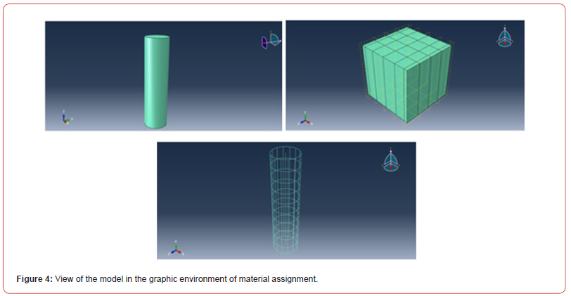
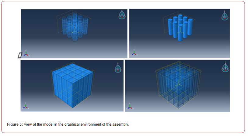
Solid element was used to model concrete parts. And steel rebars from wire elements were used. The modulus of elasticity of steel is 199 GPa and the concrete used in this modeling is concrete with enclosed behavior with a compressive strength of 25 MPa for samples A, B, C, and D. After defining the specifications of concrete and steel materials in this module, the assignment of materials is done, after defining the materials and correctly assigning the desired model in the graphic environment of the Abaqus program, it turns green, in Figure 4, you can see the assignment of materials to the desired model did. The assembly module is used to assemble the model, in this part, the parts of each part of the model are produced and they are assembled. After completing the assembly of the model, the final shape of the model can be seen in the graphical environment of the assembly (Figure 5).
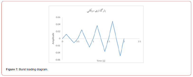
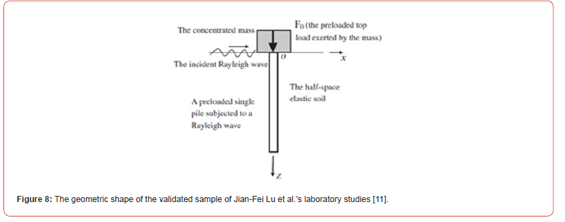
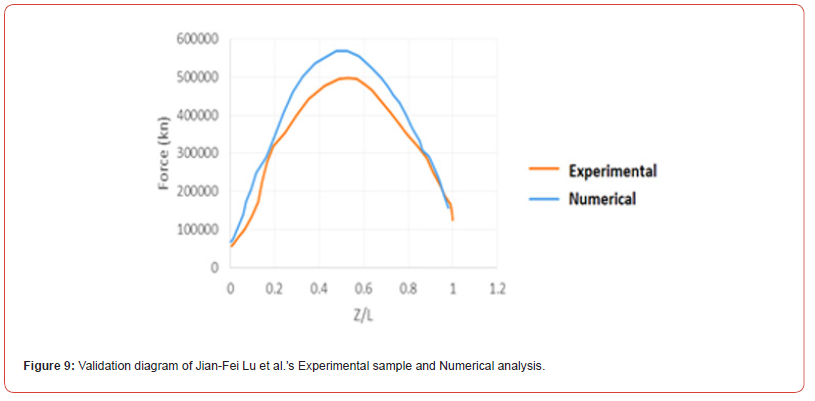
In the mesh module, the meshing of the model is done, the size of the assigned meshes was considered to be 50 mm, in Figure 6, the method of meshing is presented. In order to analyze the explosive dynamic of the studied models of samples A, B, C, D, it is necessary to define the loading type of Figure 7 for all samples A, B, C, D in the loading module. For the accuracy of the Abaqus software sample, the laboratory studies of Jian-Fei Lu and colleagues in 2010 were used, by comparing two hysteresis charts, it was observed that the difference in resistance of the two samples was about 5%, which is a very small and insignificant difference. Was. Figure 8 shows the specifications of the validation model and the hysteresis diagram (Tables 7-9).
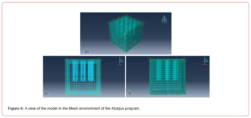
Table 7:Concrete mechanical characteristics of pile group modeling sample.

Table 8:Value of change of position under pile group of study models A, B, C, D.

Table 9:Strain value of study models A, B, C, D.

Analysis Results
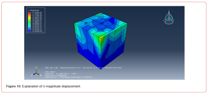
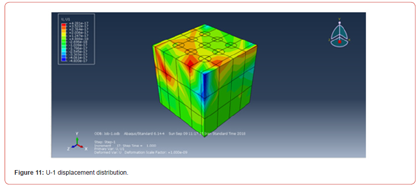
After performing the analysis in an explicit way, you can use the visualization environment of Abaqus software to view the analysis results. In the figure, you can see the output and contour of different analysis parameters of model A, B, C, D. In Figure 9, the overall displacement contour (U-magniude) of the sample is shown, which is clear that the combined displacements at the end and corners of the soil are more displacements under explosive loads (Figure 10). In Figure 11, the displacement contour of U-1 model of the study sample is presented. The maximum displacement stresses occurred in the continuous environment of the pile and soil, and more displacements were created in the central part of the displacement.
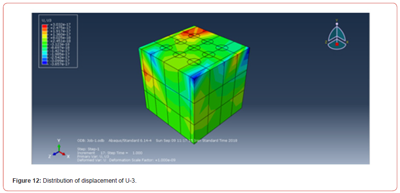
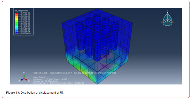
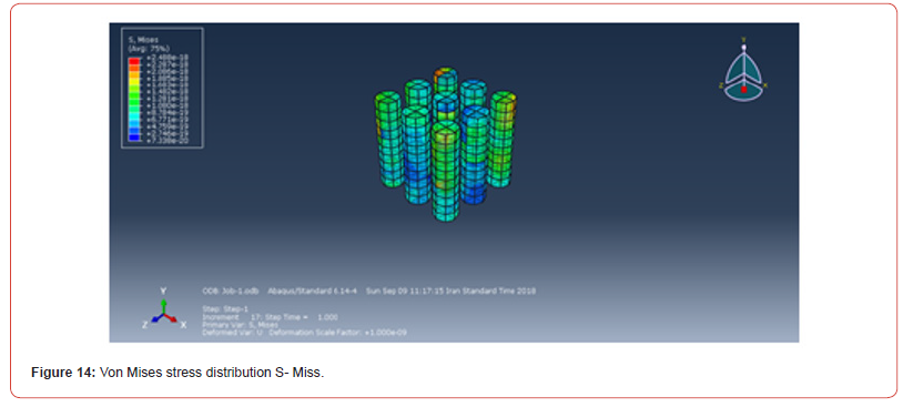
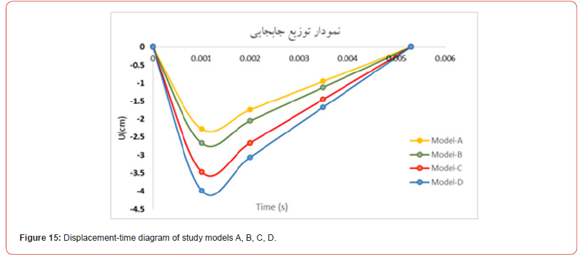
In Figure 12, the maximum displacement stresses occurred in the corner of the second quarter of the continuous environment of the pile and soil, and in the central part, the displacements of the soil are less than the displacements created. In Figure 13, the response contour of a support is shown. It has been determined that the maximum support reaction stresses are created in the central part of the soil and the sides bear less support reaction. Figure 14 shows the von Mises stress distribution contour of the study sample model. It has been determined that the stresses created in corner piles are much higher than the stresses created on concrete piles. This article shows that the tensions generated in the end parts are much higher than the central parts due to the location of the explosion load. In Figure 15, you can see the diagram (displacement-time) of study sample A (clay soil + 25% porosity), study sample B (clay soil + 50% porosity), study sample C (sandy soil + 25% porosity) and study sample D (found sandy soil + 50% porosity. According to the comparison of the displacement-time diagram of model A (clay soil + 25% porosity) and model B (clay soil + 50% porosity), it was observed that with the change in the percentage of displacement of piles in clay soil with 50% porosity compared to 25% porosity, 23.47% increase in the displacement of the end of the candle. Also, according to the comparison of the displacement-time diagram of model C (sandy soil + 25% porosity), and model D (sandy soil + 50% porosity), it was observed that with the variation of the percentage of pile base displacement porosity in sandy soil with 50% porosity compared to 25% porosity, it causes an increase of 25.38% in the displacement of the end of the pile (Table 10).
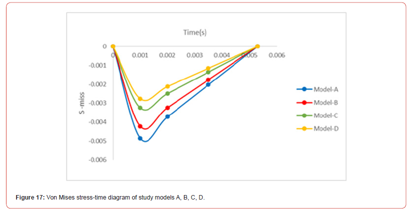
Table 10:Von Mises stress values - time of study models A, B, C, D.

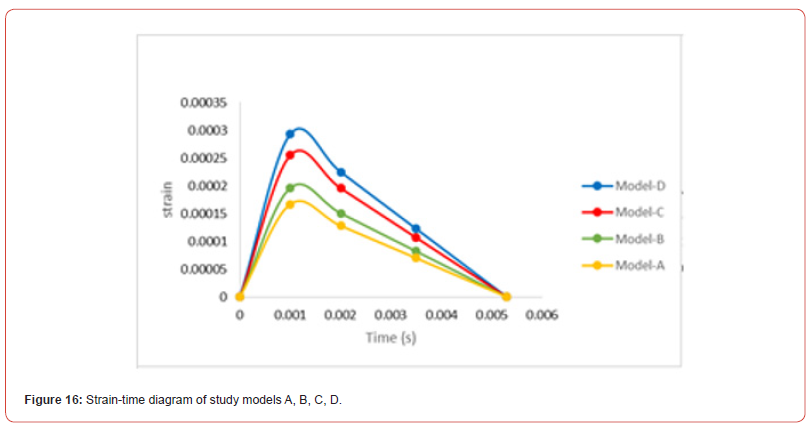
Also, according to the comparison of the displacement-time diagram of model A (clay soil + 25% porosity), and model C (sandy soil + 25% porosity), it was observed that by changing the type of granular soil to cohesive, the displacement in granular soils increased by 18.95%. It becomes. In Figure 16, you can see the diagram (strain-time) of study sample A (clay soil + 25% porosity), study sample B (clay soil + 50% porosity), study sample C (sandy soil + 25% porosity) and study sample D (soil observed sandy + porosity 50%). According to the comparison of the strain-time diagram of model A (clay soil + 25% porosity) and model B (clay soil + 50% porosity) it was observed that by changing the percentage of porosity, the displacement of piles in clay soil with 50% porosity compared to 25% porosity, He saw an increase of 26.71% strain. Also, according to the comparison of the strain-time diagram of model C (sandy soil + 25% porosity), and model D (sandy soil + 50% porosity), it was observed that with the change of the percentage of porosity, the displacement of the pile base in sandy soil with 50% porosity compared to 25% porosity, causes the strain to increase by 24.36%. Also, according to the comparison of the strain-time diagram of model A (clay soil + 25% porosity) and model C (sandy soil + 25% porosity), it was observed that by changing the type of granular soil to cohesive, the strain decreases by 17.53%.
In Figure 17, you can see the diagram (Von Mises stress-time) of study sample A (clay soil + 25% porosity), study sample B (clay soil + 50% porosity), study sample C (sandy soil + 25% porosity) and study sample D (sandy soil + 50% porosity). According to the comparison of the stress-time diagram of model A (clay soil + 25% porosity) and model B (clay soil + 50% porosity) it was observed that with the change of the percentage of porosity, the displacement of piles in clay soil with 50% porosity compared to 25% porosity caused 23.74% reduction of von Mises stress. Also, according to the comparison of the stress-time diagram of model C (sandy soil + 25% porosity), and model D (sandy soil + 50% porosity), it was observed that with the change in the percentage of porosity, the displacement of the pile base in sandy soil with 50% porosity compared to 25% porosity, the von Mises stress is reduced by 20.68%. Also, according< to the comparison of the strain-time diagram of model A (clay soil + 25% porosity) and model C (sandy soil + 25% porosity), it was observed that by changing the type of granular soil to cohesive, it caused an increase of 16.34% in the Von stress. It will disappear.
Conclusion
a. In this research, four study samples A, B, C, D were used,
study sample A (clay soil + 25% porosity), study sample B
(clay soil + 50% porosity), study sample C (sandy soil + 25%
porosity) and They constituted the study sample D (sandy soil
+ 50% porosity), and the following results were obtained:
b. With an increase of about 25% in the percentage of
porosity in sticky soils (clay), the displacement of the pile base
increased by about 24.42% on average.
c. With an increase of about 25% in the percentage of
porosity in granular (sandy) soils, the displacement of the pile
base increased by about 25.53% on average.
d. By changing the type of soil from granular (sand) to sticky
(clay), with a fixed percentage of porosity, the end displacement
of the pile increased by 18.95% on average.
e. With an increase of about 25% in the percentage of
porosity in sticky soils (clay), the base strain of the piles
increased by about 23.75% on average.
f. By changing the type of soil from granular (sand) to sticky
(clay), with a fixed percentage of porosity, the end strain of the
pile increased by 21.63% on average.
g. With an increase of about 25% in the percentage of
porosity in sticky soils (clay), the von Mises stress of the pile
base increased by about 20.81% on average.
h. By changing the type of soil from granular (sand) to sticky
(clay), with a constant percentage of porosity, the Von Mises
stress at the end of the pile increased by 19.74% on average.
i. According to the change of dimensions of piles, it was
observed that by increasing the diameter and dimension of piles
by 20%, the strength of concrete piles increased by 17.52%.
References
- Jafari, Mohammad Mostafi, Omid Pourabrahim (2016) Comparison of the bearing capacity of fine in-situ concrete pile walls with rammed stone columns in sandy clay soil, 5th National Conference on Civil Engineering, Architecture and Sustainable Urban Development, Tehran, Mehr Arvand Institute of Higher Education and the center of sustainable development solutions.
- Heydarian Amir (2015) Investigation of the effect of pile and soil interaction under dynamic load, International Conference of Elites of Civil Engineering, Architecture and Urban Planning, Tehran, Saramed Homaysh Karin Institute.
- Khalki Fard, Mehrdad, Sina Rasouli (2015) The Effect of soil shear strength parameters on pile bearing capacity under dynamic load, the second international conference on new research findings in civil engineering, architecture and urban management, Tehran, International Confederation of Inventors of the World (IFIA), University of Applied Sciences.
- Rahi, Mohsen, Mehdi Meshaal (2016) Investigation of displacement changes in the length of the pile according to the depth and amount of load in clay and sandy soil, the second national conference of new research and educational findings of civil architecture, urban planning and environment in Iran, Tehran the permanent secretariat of the conference.
- Changjie Zheng, George P Kouretzis, Scott W Sloan, Hanlong Liu, et al. (2015) Vertical vibration of an elastic pile embedded in poroelastic soil, Soil Dynamics and Earthquake Engineering 77: 177-181.
- Han-Jiang Lai, Jun-Jie Zheng, Rong-Jun Zhang, Ming-Juan Cui (2018) Classification and characteristics of soil arching structures in pile-supported embankments, Computers and Geotechnics 98: 153-171.
- Hyunwook Choo, Hwandon Jun, Hyung-Koo Yoon (2018) Porosity estimation of unsaturated soil using Brutsaert equation, Soil Dynamics and Earthquake Engineering 104: 33-39.
- Jian Fei Lu, Xu Zhang, Jian Wei Wan, Nai Rui Cang (2011) The influence of a fixed axial top load on the dynamic response of a single pile. Department of Civil Engineering, Jiangsu University, Zhenjiang, Jiangsu, PR China.
- Xiang-Lian Zhou, Jian-Hua Wang, Ling-Fa Jiang, Bin Xu (2009) Transient dynamic response of pile to vertical load in saturated soil. Department of Civil Engineering, Shanghai Jiao Tong University, Shanghai, China.
- Xuanming Ding, Lubao Luan, Changjie Zheng, Wei Zhou (2017) Influence of the second-order effect of axial load on lateral dynamic response of a pipe pile in saturated soil layer, Soil Dynamics and Earthquake Engineering 103: 86-94.
- Jian Fei Lu, Xu Zhang, Jian-Wei Wan, Nai-Rui Cang (2012) The influence of a fixed axial top load on the dynamic response of a single pile, Computers and Geotechnics 39: 54-65.
-
Seyed Ali Mousavi Davoudi*. Studying and Investigating the Effect of Soil Porosity on the Dynamic Behavior of Reinforced Concrete Piles under Explosive Load. Cur Trends Civil & Struct Eng. 10(2): 2024. CTCSE.MS.ID.000736.
-
Reinforced concrete pile; dynamic behavior; soil-structure interaction; soil porosity; Iris Publishers, Iris Indexing Sites
-

This work is licensed under a Creative Commons Attribution-NonCommercial 4.0 International License.


