 Research Article
Structural Performance of Channel and Angle Shear Connectors in Brick Aggregate Concrete
Md Rabiul Alam1* and Mostafa Humayun Akram2
1Professor, Department of Civil Engineering, Chittagong University of Engineering & Technology, Chittagong, Bangladesh
2Outgoing undergraduate student, Department of Civil Engineering, Chittagong University of Engineering & Technology, Chittagong, Bangladesh
Md Rabiul Alam, Professor, Department of Civil Engineering, Chittagong University of Engineering & Technology, Chittagong, Bangladesh.
Received Date:January 09, 2023; Published Date:January 20, 2023
Abstract
This study is based on the necessity of sustainable housing in earthquake-prone and wind-prone coastal locations. It focuses on determining the load-slip behavior, failure mode, and ductility of low-strength concrete made with brick aggregate containing channel and angle shear connectors fixed with the wide flanged beam. Under monotonic loading, channel connectors have an average of 15.11% and 54.81% higher shear capacity and slip than angle connectors in brick aggregate concrete slab. Shear loads from experiments are compared with some formulas. It is found that formulas give slightly higher results than experimental results for both channel and angle shear connectors of the brick aggregate concrete.
Keywords: Composite structure; Push-out test; Monotonic loading; Energy absorption
Introduction
A growing middle class with higher housing needs is difficult for developing countries, particularly those in Asia (Bangladesh). More innovation is being incorporated into building and construction techniques to lower construction costs and produce affordable homes. In the coastal site, the people’s livelihood is below the poverty line. Floods, tides, and tsunamis are regular phenomena in coastal areas. So, the coastal people must reconstruct their houses every time disasters occur. Therefore, low-cost sustainable building construction is urgent for them. Construction techniques that are quicker and cheaper are being sought for emergency response. Since Bangladesh has a dearth of high-quality stone, stone aggregates are imported from other countries. Brick is ubiquitous and available in this country. The total cost will be reduced if the brick aggregate is used for the low-rise composite building construction. Composite structures are less expensive and less time-consuming than conventional RCC buildings. Compared with RCC structures, composite structures save 32.02% in construction time, thereby saving total cost [1].
With the increased demand for load-carrying capacity, aesthetics, environmental sustainability, safety, and reliability in an industrial building, especially in apparel industries, where many people work in a reasonably small space, it has become imperative to construct a composite structure. In a composite structure, the primary key parameter is the longitudinal shear transfer between concrete and steel components. It comes from three main mechanisms: a) chemical bonding, b) friction, and c) mechanical interaction of interfacial media. Chemical bonding is often ignored in both design and analysis of composite structures, but friction and mechanical actions are crucial [2]. Mechanical action is achieved only by providing shear connectors between concrete and steel components. Structural behavior of angle shear connectors with dissimilar orientations like 45° and 90° and concluded that the 45° angle shear connector presents less scatter than the 90° angle shear connector [3]. Since shear connectors are inserted into the concrete, the properties of concrete are mainly responsible for the shear load receiving part. Usually, the shear connector transfers longitudinal shear to the concrete strata and helps the steel beam to carry a higher load by effectively increasing the compression area or activating slab reinforcement in the tension and compression zones. Its strength plays a vital role in making the entire system more effective, as shear connectors are usually made of mild steel.
Earlier Studies on the Behavior of Shear Connector in Composite Construction
Viest [4] and Johnson [5] published research reviews on composite beams conducted from 1920 to 1958 and 1960 to 1970, respectively. Moore [6] discussed composite buildings in the United States. The flexural behavior of composite beams is well recognized and reported in several sources [7,8]. he Canadian Standard for developing composite beams includes several additional provisions [9]. Some of these changes reflect current North American research findings, while others recognize the need to add criteria similar to those found in Eurocode 4 [10]. The guidelines for designing composite beams in the Canadian standard mostly apply to simply supported beams where concrete is compressed. Viest [11] published the results of forty-three push-out tests on full-size specimens using C-shape shear connectors. The strength of concrete varied from 14-44 MPa. They focused on describing channel shear connectors’ behavior and determining whether or not employing channels as shear connectors was feasible. According to the test findings, the channel connector’s behavior was impacted by the flange thickness, web thickness, and channel length. The orientation of the channel connector, i.e., whether the load was applied to the front or rear of the channel, had no significant effect on the channel shear connector’s performance.
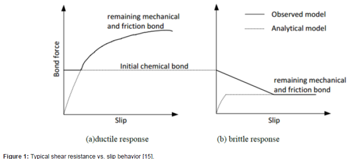
Soty & Shima [12] proposed some equations for different strut angles (20° ≤ θ ≤ 45°) of only L-shape shear connectors. An exponential equation to forecast the enveloped curve was suggested. The final relative displacement was around 0.02 times the shear connector’s height regardless of the shear connector’s size, the concrete’s strength, & the strut angle. He found two modes of failure, split and shear failure mode, guided by strut angle and shear connector’s thickness-to-height ratio. Rao [13] provided the test findings for the small-scale push-out specimens with channel shear connectors. According to the findings of his tests, compared to flexible connectors of the headed stud type, channel shear connectors offered flexibility and high load-bearing capability. Using a channel connector in a vertical orientation would be preferable since it would offer resistance to uplift, eliminating the need for a hoop and giving a more flexible shear connection. Hawkins & Mitchell [14] suggested shear connectors between concrete slab and steel section for composite action in flexure. They can also convey the slab’s massive horizontal inertial forces to primary lateral loadresisting components. Four different failure modes are narrated for metal deck stud shear connectors. Envisioning the strengths associated with those failures is derived from some equations. It is indicated that the types of failure dramatically influence the strength, ductility, and reversed cyclic loading response. According to Daniels & Crisinel [15], shear connectors between the deck and beam increase mechanical bond stresses above chemical bond stresses. The response to these mechanical devices is ductile. Without these mechanical devices, the response is brittle. Pullout and push-off tests estimated the behavior and strength of the connection betwixt the deck and concrete slab. Figure 1 depicts shear resistance vs. slip behavior for shear connectors according to Daniels and Crisinel (Figure 1).
Lungershausen [16] has developed model to demonstrate the load transmission of stud connector in solid slab application. The connector in Figure 2 has a total capacity that is made up of four separate components. In the first instance, a significant percentage of the longitudinal shear force reacts with the weld collar directly after traveling from the bottom of the stud into the nearby concrete (A). Multi-axial high bearing loads cause the concrete at the stud’s foot to crush. Then the stud’s shank (B) redistributes the shear forces higher up. The connector’s base is free to move sideways, but the stud’s top is embedded in unaltered concrete and cannot deform, causing bending and tensile stresses in the stud’s shank (C). Compressive pressures in the concrete under the stud head counterbalance tensile stresses, activating additional frictional forces (D) at the steel-concrete contact. The shear connection fails when stud shank has merged shear-tension failure above the weld collar (Figure 2).

According to Xue et al. [17], when loaded, the stud shank experiences bending moment, shear force, axial force, and stretching and flattening at the root area. As a steel beam slides against a concrete slab, the stud rotates and deforms the concrete at its end. The stud’s rotation is likewise limited by the concrete around it. As the specimen load increases, the steel beam-to-stud load increases continually. Hidehiko & Hosaka [18] reported on an experimental investigation conducted in Japan on flexible shear connectors in composite girder bridges. They found that flexible shear connectors were particularly effective in lowering tensile stresses created in the negative moment areas of a continuous span bridge’s intermediate supports. This connector also performed well in fatigue load resistance, particularly on bridges. However, little is known about how these shear connectors react when embedded in regular concrete and the moderately low-strength concrete often utilized in composite structures. Receiving monotonic loading & fully reversed cyclic loading, Shariati et al.[19,20] examined the performance of C-shape and L-shape shear connectors in order to transfer the longitudinal shear loads via steel-concrete interface in composite beams. Under monotonic loading, the angle connector displayed 7.5-36.4% less shear load compared to the channel connector. Angle and channel connector both displayed fracturetype failure. Following the failure, slab with channel cracked more than angle. All the channel connectors had enough ductility. But the angle connectors had lower ductility. Using reinforcements in the concrete slabs increased the shear capacity and ductility of the composite system. So far, all those experimental studies have been done for the stone aggregate concrete. The study of composite structures with brick aggregate concrete is almost new.
Experimental Study
Materials
Table 1:Physical properties of coarse aggregate.

Table 2:Geometric properties of wide flange steel girder and shear connectors.
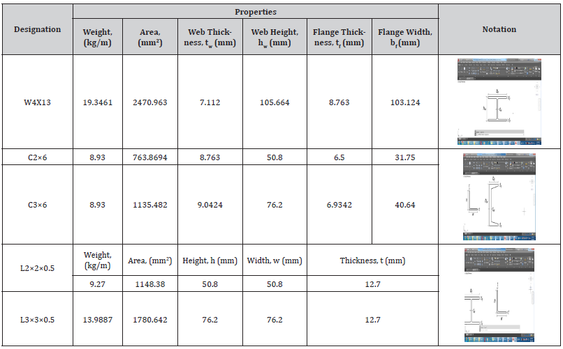
Several tests were performed on the materials used in the experimental study. Ordinary Portland cement was used to cast the concrete slabs. The 28-day compressive strength of cement was 25 MPa. Well-graded brick aggregates passed through3⁄4″ sieve size and retained in 1⁄2″, 3⁄8″and No.4 sieves were used as coarse aggregate. Local sand with a Fineness Modulus (FM) of 1.75 and specific gravity of 2.61 was used as a fine aggregate of concrete. The coarse aggregate’s physical properties are shown in Table 1. Mix proportions of 1:2.25:4 was used to cast the concrete slabs within28 days of curing. This concrete mix proportion was determined by following the ACI mix design method [21]. A standard cylinder (diameter = 150 mm, length = 300 mm) is used to find out the 28-day compressive strength of concrete. Steel rebar (yield strength = 413.69MPa) was embedded within the concrete slabs as longitudinal and tie bars. Only One type of wide flange steel girder and two types of angle and channel shear connectors with different lengths were used in this study. The slab thickness often needs to be minor; in that case, it is quite impossible to use the AISC steel construction manual [22]. As per practical use and measurement, small dimension shear connectors have been used. So, the channel and angle shear connectors are made separately without following the AISC steel construction manual. ASTM standard A992 rolled section (yield strength = 344.74 MPa, fracture Strength = 448.16 MPa)was used for wide flange steel girder and shear connectors. The average result of three cylindrical compressive strength test specimens of brick aggregate concrete was 20MPa. The geometric properties of wide flange steel girder and shear connectors are described in Table 2 (Tables 1,2).
Preparation of Test Specimens
In the current test program, a total of 12 test specimens divided into four series were cast. All four series are summarized in Table 3. Each of the two series was designed for angle and channel shear connectors with different lengths of brick aggregate concrete slab. Conventional welding welded these shear connectors to the W-shape girder. Figure 3 displays the longitudinal bar with stirrup and shear connectors welded with the W-shape girder (L2, L3, C2, and C3). The W-shape girder had a length of 304.8mm. To form the steel skeleton, Ø16 mm and Ø10 mm steel rebar were used as longitudinal bars and stirrups, respectively. The stirrups had a spacing of 76.2mm c/c and a clear cover of 12.7mm. Wooden formwork was made to cast the concrete blocks designed to prototype concrete slabs. The formwork had an inner dimension of254×203.2×406.4mm. The shear connectors, along with the W-shape girder, were placed within the steel skeleton of concrete slab and then placed within the wooden formwork. After placing the steel profile, the remaining open sides were closed by sliding wooden parts. Fresh concrete was mixed and poured into the prepared formwork. Concrete was poured layer by layer and at each layer, sufficient temping was made using a steel rod. Curing was performed by submerging each specimen under clean water for 28 days. Figure 4 shows the pictures of reinforced slab steel with W-shaped girder and after removing the formwork (Table 3) (Figures 3,4).


Table 3:Description of test specimens.

Table 4:Comparison of ultimate shear capacity of shear connectors having different shapes and lengths of brick concrete slab.

Instrumentation and Testing Procedure
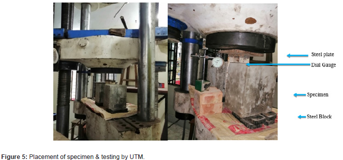
All 12 push-out tests were accomplished in Universal Testing Machine (UTM) to obtain load-slip data and observe the failure mechanism of a specimen following the design standards – British BS5950 [23]. The UTM had a capacity of 2000kN. A cylindrical solid steel block of 100 mm in height and diameter of150 mm was placed on the UTM lower platform under each concrete slab, supporting the specimen. The solid steel plate was 25 mm thick. It set at the top of the W-shape girder to distribute the load uniformly. The monotonic load was gradually increased with a fixed displacement rate of 0.01 mm per second until the specimen began to fracture and fail. A magnetic dial gauge was in between the upper face of slab and the bottom face of upper platform of UTM to record the slip. Each specimen’s load and slip results were recorded manually from the load display of the UTM and magnetic dial gauge, respectively. The load was applied vertically upward from the block’s bottom platform, and the steel profile was resisted at the static top platform of UTM. Due to the application of monotonic load, the steel profile started to slip down against the adjacent concrete slab and the deflection was measured from the dial gauge. The slip of the steel profile was measured at an interval of 10kN. The test configuration is shown in Figure 5 (Figure 5).
Results and Discussion
Load-slip behavior
Average load-slip curves (obtained from one set of three specimens) of all four series are shown and compared in Figure 6. As can be seen, all the shear connectors have a similar trend in results for brick aggregate concrete specimens. The shear capacity increases with the length of the shear connectors. With the increase in load, the slip value increases to reach a maximum shear load and after that, the load decreases. Beyond the ultimate shear load, the load capacity drops quickly. Further, the short-length shear connectors (L2and C2) have comparatively flat curves, indicating that shear connectors having longer lengths have higher stiffness. It is also noticed that the shear connectors experience different slip values at the ultimate shear load. The ultimate shear resistance and slip values are determined and compared to obtain a clear idea about the load-slip behavior. Comparisons of ultimate shear capacity maximum slip of the shear connectors having different shapes and lengths of brick aggregate concrete are shown in Table 4 and Table 5, respectively.
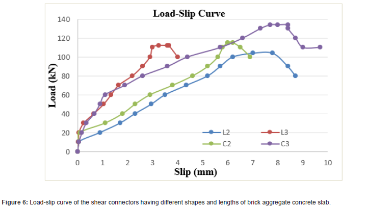
Table 5:Comparison of maximum slip of shear connectors having different shapes and lengths of brick aggregate concrete slab.s

Table 6:Equations for estimating shear capacity of the L-shape and C-shape shear connector.

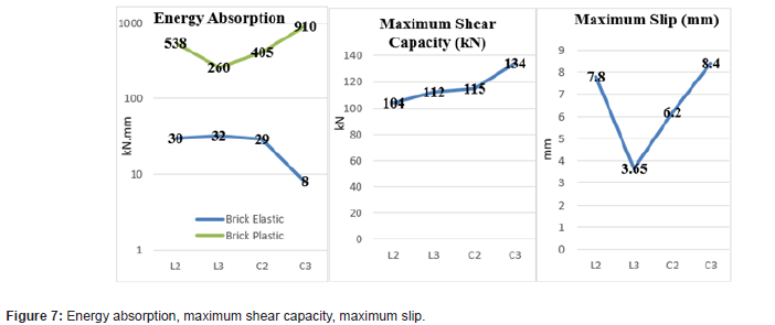
In case of C-shape shear connectors, the C3carries a mean load of 134kN, while the C2 carries 115kN (a decrease of 14.18% in the ultimate shear capacity). A mean load of 112kN is carried by the L3 specimen, whereas the L2 carries104kN (a decrease of 7.14% in the ultimate shear capacity). This could be because shorterangle connectors centralized the applied load on a smaller region. The specimen with C3 is more flexible than the one with C2. At the ultimate load, the C3 had 8.4 mm of slip compared to 6.2 mm slip for the C2 (which means a decrease of 26.19% in slip). The specimen with L3 is more flexible than that of L2. The slip value at the ultimate load for the L3 was 3.65 mm, compared to 7.8 mm for the L2 (which means an increase of 113.69% in slip). The channel shear connectors having the same length have a much higher shear capacity than the angle. For the ultimate shear capacity, L3, C3, C2, and C3 are 7.69%,16.52%,10.58%, and 19.64% higher than L2, C2, L2, and L3, respectively. For the slip, L3 and C2 are 53.20% and 20.50% lower than L2, respectively. Moreover, C3 is 35.48% and 130.13% higher than C2, and L3, respectively. The ductility of the structural member is an essential mechanical criterion that is always desirable in steel-concrete composite construction and is inherently connected to the slip value. A ductile member usually displays large deformation or slip before failing to warn the users. According to Eurocode 4, the slip characteristics must be at least 6 mm for a shear connector to be considered ductile. Based on these criteria, almost all the considered shear connectors are ductile. However, the C-shape shear connectors are more ductile than the L-shape connectors, and ductility increases with shear connector’s length (Figure 6) (Tables 4,5).
Energy absorption
Energy absorption values are determined from load-slip values. The area under the load-slip curve is used to calculate the energy absorption. Both elastic and plastic energy absorption occurred in load slip behavior. Elastic energy absorption is found to be smaller than plastic energy absorption. But elastic energy absorption is too little in brick aggregate concrete slabs. The energy absorption curve, maximum shear capacity, and maximum slip are shown in Figure 7 (Figure 7).
Comparison of experimental and theoretical value
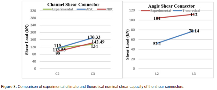
Some analytical equations are required to design and evaluate the shear capacity of shear connectors, as it is not always possible to test. AISC (2005) [24] and National Building Code, Canada (NBC) [25] have already derived several equations for calculating nominal shear capacity of C-shape connectors. Kiyomiya and Yokota [26] provided an empirical formula for estimating the nominal shear capacity of L-shape connectors. Table 6 describes equations and explains the precise terms. A comparison is made between the experimental and the theoretical shear capacity to check the reliability and performance of these equations for further application, shown in Table 7 and Table 8. Figure 8 compares the experimental ultimate and the theoretical nominal shear connectors’ shear capacity. As can be seen, the proposed equations predict the shear capacity marginally. The theoretical equations given by NBC, AISC-2005, Kiyomiya and Yokota underestimated most of the shear capacity obtained in the study (Table 6).
Table 7:Comparison of the shear capacity between the experimental values with theoretical values of channel (C-shape) shear connectors of brick aggregate concrete slab.

Table 8:Comparison of the shear capacity between the experimental value with theoretical value of angle(L-shape) shear connectors of brick aggregate concrete slab.

In Table 6, L-shape = angle shear connector, C-shape = channel shear connector, Qn= nominal shear of channel shear connectors, P= nominal shear of angle shear connectors, tf= shear connector’s flange thickness, tw= shear connector’s web thickness, Lc= length of shear connectors, Ec=modulus of elasticity of the concrete, fc=cylindrical compressive strength of the concrete (Tables 7,8) (Figure 8).
Failure pattern
Push-out specimens’ most prevalent failure modes are connector fracture, crushing, and splitting. Angle and channel shear connector failure modes were remarkably similar. Due to connector fracture, both connector types failed. However, the channel connectors failed with greater ductility under monotonic loading than the angles for concrete slabs. A longitudinal crack developed along the slabs as the specimens were loaded further, this crack eventually progressed and broke open due to the increased load. Connectors that yield at larger loads were observed in maximum of the experiments. The failure patterns of concrete specimens are alike. They crack in the bottom of the specimen beside the shear connectors. Under monotonic loading, the crack initiates in the form of an inclined shear crack, and with the increase in load, it propagates along the concrete slab’s depth (horizontal direction). With the increment of load, the inclined crack turns into a vertical longitudinal crack and progresses parallel to the slab (vertical direction) up to the bottom. At the point of the ultimate shear load, the opening of the cracks becomes intense, and the concrete at the side face near the shear connectors is crushed. As a result, the concrete slab is split into two distinct parts (upper and lower slabs). Figure 9 displays the failure pattern of L3 and C3 broken specimens. The concrete crushing at the side of the concrete slab is observed in those figures. The fracture failure occurs conventionally for both shear connectors of brick aggregate concrete slabs. After the collapse, there was more cracking in channels than in angles for brick aggregate concrete slabs (Figure 9).

Conclusions
The stone is almost unavailable in third-world countries like
Bangladesh, and most of the stone aggregate is imported from
other countries. Therefore, making a building of stone aggregate
is very expensive. Instead, bricks are ubiquitous and plentiful
in Bangladesh. So, the total building cost is meager if the brick
aggregate is used in the composite structure. However, for the highrise
building, it is not suggested to use brick aggregate. In the coastal
areas, the low-rise composite buildings of 4-5 stories can be made
of brick aggregate concrete and reduce the cost to a considerable
level. The main findings of the study are as follows:
1. Lengths and types of the shear connectors affected the
ultimate shear capacity and slip without any variation in failure
mode in the low-strength brick aggregate concrete slabs.
2. The channel shear connectors possessed higher shear
capacity compared to the angle shear connectors of the
duplicate length.
3. If length of the shear connector increases, the shear
capacity increases.
4. All the shear connectors were found to be ductile.
However, the specimen’s ductility increases with the increase
in the connector’s length.
5. Elastic energy absorption is found to be less than plastic
energy absorption. However, elastic energy absorption is too
little in brick aggregate concrete slabs.
6. The theoretical formulas predict the shear capacity
marginally. The equations given by NBC, AISC -2005, Kiyomiya
and Yokota underestimated the shear capacity obtained in the
study.
7. Each connector of the concrete slabs exhibits shear, split,
and crushing failures.
Acknowledgment
The entire research work has been carried out under the financial support of Department of Civil Engineering, Chittagong University of Engineering & Technology (CUET).
Conflict of Interest
No conflict of interest.
References
- B Rajput, M Hussain, Shaikh Nadar Nissar, Vadodaria Jeet (2013) Time and Cost Comparison of Construction of RCC, Steel and Composite Structure Building., Search.Ebscohost.Com. (nd).
- MR Salari, E Spacone, PB Shing, DM Frangopol ((1998)) Nonlinear Analysis of Composite Beams with Deformable Shear Connectors, Journal of Structural Engineering. 124: 1148–1158.
- D Arévalo, L Hernández, C Gómez, G Velasteguí, E Guaminga, e al. (2021) Structural performance of steel angle shear connectors with different orientation, Case Studies in Construction Materials. 14: e00523.
- IM Viest (1960) Review of Research on Composite Steel–Concrete Beams, Journal of the Structural Division. 86: 1–21.
- RP Johnson (1970) Research on Steel-Concrete Composite Beams, Journal of the Structural Division. 96: 445–459.
- WMCC S and Concrete undefined (1987) An overview of composite construction in the United States, Cedb Asce Org (nd)
- EYL Chien, JK Ritchie (1984) The CISC publication entitled: Design and Construction of Composite Floor Systems, nd.
- GL Kulak, GY Grondin (2011) Canadian Institute of Steel Construction, Limit states design in structural steel, Canadian Institute of Steel Construction.
- CAN/CSA-S16.1-M8 (nd) (2022).
- N Europeenne (2004) European Standard Eurocode 4: Design of composite steel and concrete structures-Part 1-1: General rules and rules for buildings.
- IM Viest ((1951)) Full-scale tests of channel shear connectors and composite t-beams, University of Illinois at Urbana Champaign, College of Engineering.
- R Soty, H Shima (2013) Performances of I-shape shear connector subjected to strut compressive force in steel-concrete composite structures, nd.
- RS Narahari (1970) Composite construction - tests on small-scale shear connectors, Inst Engrs Civil Eng Trans.
- NM Hawkins, D Mitchell (2010) Seismic Response of Composite Shear Connections, Journal of Structural Engineering 110 (1984): 2120–2136.
- BJ Daniels, M Crisinel (1993) Composite Slab Behavior and Strength Analysis. Part I: Calculation Procedure, Journal of Structural Engineering. 119: 16–35.
- H Lungershausen (1988) ZurSchubtragfähigkeit von Kopfbolzendübeln, Mitteilung Nr. 87-88.
- W Xue, M Ding, H Wang, Z Luo (2008) Static Behavior and Theoretical Model of Stud Shear Connectors, Journal of Bridge Engineering. 13: 623–634.
- H Abe, T Hosaka (2000) Flexible Shear Connectors for Railway Composite Girder Bridges, Proceedings of the Conference: Composite Construction in Steel and Concrete IV, pp.71–80.
- Ali Shariati (2012) Investigation of channel shear connectors for composite concrete and steel T-beam, International Journal of the Physical Sciences.
- M Shariati, NH Ramli Sulong, A Shariati, MA Khanouki (2016) Behavior of V-shaped angle shear connectors: experimental and parametric study, Materials and Structures/Materiaux et Constructions. 49: 3909–3926.
- ACI, 211.1-91 (2009) Standard practice for selecting proportions for normal, heavyweight, and mass concrete.
- Specification for Structural Steel Buildings, Specification for Structural Steel Buildings (2010).
- P BS5950, 3-1 (1990) Structural use of steelwork in building: Code of practice for design of simple and continuous composite beams, London: British Standards Institution.
- Aisc (2005) AISC Specification for Structural Steel Buildings.
- Canadian Commission on Building and Fire Codes (2005) Institute for Research in Construction (Canada), National building code of Canada.
- YH Kiyomiya (1986) Strength of shear connector by shape steel in composite member with steel and concrete, in: Proc. of Symposium on Research and Application of Composite Constructions, JSCE, pp.113-118.
-
Md Rabiul Alam* and Mostafa Humayun Akram. Structural Performance of Channel and Angle Shear Connectors in Brick Aggregate Concrete. Cur Trends Civil & Struct Eng. 9(4): 2023. CTCSE.MS.ID.000716.
-
Composite structure, Push-out test, Monotonic loading, Energy absorption
-

This work is licensed under a Creative Commons Attribution-NonCommercial 4.0 International License.


