 Practical Guide
Pre-Grouting for Tunnels in Jointed Rock
Nick Barton, NB&A, Norway,.
Received Date:April 20, 2023; Published Date:May 04, 2023
Abstract
Pre-grouting is an effective way of displacing water and severely limiting inflow to tunnels, if practiced correctly. Joint sets are successively sealed, and permeability tensors are known to rotate and reduce in magnitude for each set. In fact, the needs for tunnel support and reinforcement are actually reduced by successful pre-grouting, but not when wet shotcrete or leaking bolt holes are seen following unsuccessful pre-injection. The possibility of dry tunnels depends on the use of stable non-shrinking grouts, with particle sizes appropriate to the estimates of mean physical joint apertures (E). Hydraulic apertures (e) estimated from permeability testing are idealized smooth parallel plates. They are smaller, mathematically derived apertures so are not realistic objectives for determining the cement particle fineness, using either ultrafine, or micro-cement, or industrial Portland cement and the experimentally proved rule-of-thumb of E needing to be greater than 4.d95. The aperture difference E ≥ e is due to hydraulic losses due to roughness. They are equal when greater than 1.0 mm. A poor pre-injection result like wet shotcrete and leaking bolt holes may also result from too low injection pressure. Local joint jacking is needed, with limited risk when flow of grout is occurring. There is a rapid pressure drop from the injection borehole out into the intersected joint planes, with at least 50% loss of pressure within 1m for Newtonian fluids, and more for rough joints using grout with its Bingham fluid cohesion and friction. However, pressure must not be held when flow has stopped. Injection pressure must obviously be lower if there are large flows near the surface or in permeable crushed zones at depth. If for some reason one is not using stable cements it will be necessary to use lower pressure anyway, but one must then expect poorer penetration and volume reduction when hardened, meaning the likelihood of wet shotcrete.
Keywords:Pre-grouting; settlement-damage; high-pressure; micro-silica; joint-apertures
Introduction
Pre-grouting ahead of tunnels has three main functions: to control inflow into the tunnel, to make tunnelling progress more predictable in case of poor-quality rock masses, and to limit groundwater drawdown above the tunnel. This helps to avoid settlement damage caused by consolidation of clay deposits beneath built up areas. Towns tend to be built where terrain is flat, due to the same clay deposits. Green areas are also largely protected if groundwater levels are maintained. The need for good pre-injection routines should be clear to all civil engineers who have seen the suffering of city commuters, house-owners, building occupants, even football stadium owners (Stockholm), and sometimes farmers and forest tourgoers (Oslo). Tunnelling may trigger groundwater drawdown and damage to infrastructure, even multiple 1m subsidence to roads near metro tunnels (São Paulo) and abandoned houses. Furthermore, and distant from cities, TBM need not get stuck in mountains (multiple instances) with good probe drilling and timely impermeabilization (pre-injection) routines. This has become increasingly possible on more recent TBM. It has taken TBM manufacturers decades to achieve, as the realization of potentially more challenging ground is more widely accepted.
Some Relevant Back-Ground Information
During extensive testing of a large number of cements for their grouting abilities twenty years ago [1], it was discovered that ideal stable non-shrinking grouts with micro-silica slurry additive have extensional viscosity. Such ideal grouts tend to be excluded from selection when tested in filter- pumps with their artificial screens that force flow-separation, and which subject the tested grout to a maximum pressure gradient in one artificial test plane, quite different from grout flow in rock joints and fractures, and different also from the NES test. These findings will be discussed in more detail later.
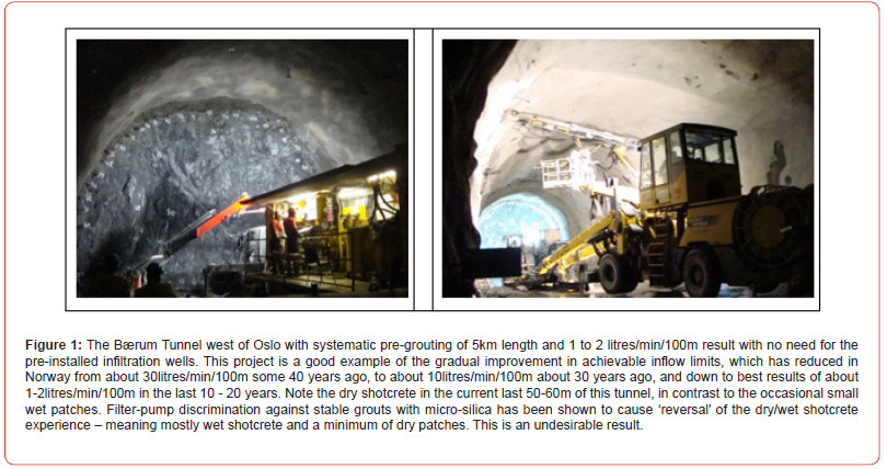
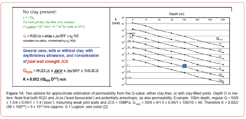
In the Bærum Tunnel west of Oslo, where inflows were in the range 1 to 2 litres/min/100m and locally lower than this, the first author had previously logged all core and related it to Lugeon data, to Q-parameters and to seismic velocities on behalf of Jerbaneverket, today’s BaneNor. The QH2O method was developed on the same occasion [2] using more than 1.4km of Lugeon test results, with lower permeability at increasing depth not only due to improved Q-values. As will be seen later a slightly altered Q-rating method is used, reversing Jr/Ja to Ja/Jr. In two earlier tunnels along the same Oslo-Asker line (Yong-Asker) the core-logging and permeability interpretation methods to be outlined in this paper were also used, enabling predictions of the different grout particle (injection cement) needs.
Settlement damage due to Groundwater drawdown in Overlying Sediments
There is an expected and logical high frequency connection between the location of towns and cities in the flatter, sedimentand- clay-filled areas, under which tunnelling is often needed. This is exactly where great care is essential (pre-injection), in preference to the optimistic: ‘We do not expect settlement damage’. The most remarkable draw-down due to tunnelling known to the authors reached 2.9 km. It was apparently transmitted from a single TBM tunnel major-inflow event and was presumably transmitted along fractured zones beneath two intersecting valleys in Sri Lanka. Thousands of houses were damaged, and hundreds of wells dried up – each in the neighboring valley. A small river used by farmers disappeared. There was no other tunnel within tens of kilometers to explain this costly phenomenon. Unfortunately, double-shield TBM, even with (or because of) reliance on bolted and gasketted PCelements, have seen instances of draw-down up to 1km distant, due to misinterpretation of permeability, sometimes in the form of subhorizontal fractures and unexpected connectivity in otherwise good quality ‘vertically fractured’ gneiss and amphibolite. The problem is the constantly repeated ‘delay’ of PC-element installation in the tail-shield, 15 to 20m distant from the advancing tunnel face. The constant advance represents a normal half, one, or two days ‘delay’ which can be extended in time if a troublesome weakness zone, or fault [3] or hard mixed face is involved, the latter causing unexpected cutter damage and delays in the maintenance cycle [4]. The unsupported section may suffer over-break.
Pre-grouting effectively reduces EDZ to prevent draw-down
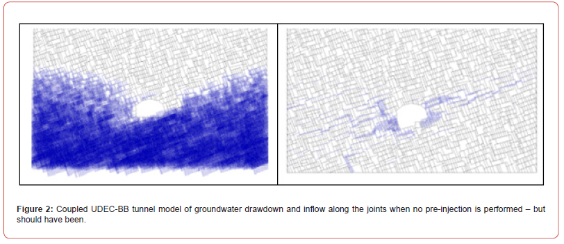
Figure 2 illustrates some coupled-process discontinuum modelling using the Itasca Inc./Dr Peter Cundall code UDEC-BB. It was performed by Dr. Karstein Monsen for a disputed case of drawdown and leakage at a metro tunnel that was not pre-injected – but should have been. The left diagram shows an example of a nearly complete drawdown of the groundwater table. On the right is the flow of water in principally the rougher and more permeable subhorizontal joints at a more limited drawdown stage.
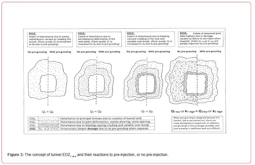
The question arises of not only how to perform pre-injection to prevent such potentially damaging drawdown (how many holes, what injection pressures, which grouting materials, which starting water/cement ratios), but also of what is actually happening when injecting cement-based grouts into the active (one diameter thick?) load-bearing rock ‘cylinder’ that will later surround the new tunnel. Figure 3 shows a diagrammatic attempt at representing the roughly ‘cylindrical’ surrounds of a tunnel to represent EDZ1, EDZ2 and EDZ3 which are each defined at the top of the figure. The idea with the symbolic and right-side and left-side sketches is to represent the potential effect of pre-injection, or not. EDZ2 represents rock joint adjustments. Permeability here is likely to be minimized by preinjection, but most important is the EDZ3 representing blast damage. This is formed after the pre-injection when the tunnel is excavated, so represents a more permeable zone (assisting drainage if still needed) on the inside of the grouted cylinder. (Note: in the ‘boxes’ the Q-value is assumed to increase as in [5], [6]).
The Benefits of Micro-Silica Additives and Evidence of the 4 X D95 Rule
Roald in [7] and [1] described extensive measurements of the penetration properties of various cement-based injection materials in a thorough analysis of some 20 manufacturer’s grouting cements. The most important physical quality-control result of this early research is that bleeding and volume loss can be reduced to negligible amounts by using micro-silica slurry additive. Figure 4 is a graphic summary of the diverging consequences of not using or using such additives.

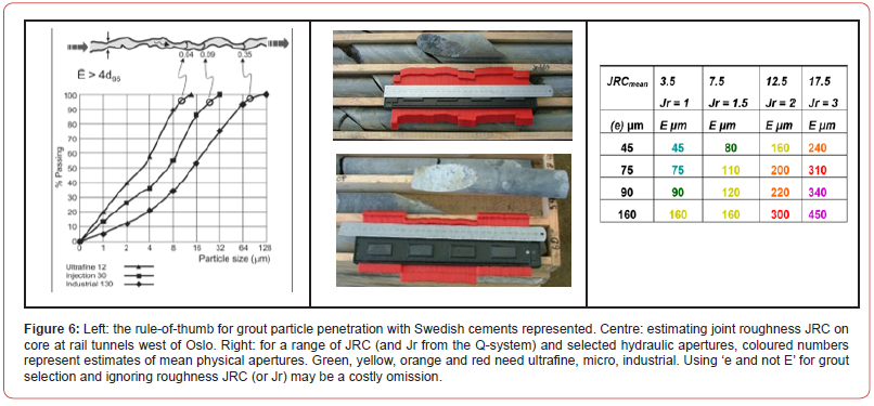
A major practical problem is that unstable grouts without micro-silica do not tolerate high-pressure injection as well as stable grouts, and they may shrink when setting due to filtration and bleeding. The filter pump was also investigated during the studies of 20 years ago [1]. Roald and Saasen found it to give inconsistent results, but worst of all it caused stable grouts to be rejected because of their resistance to flow separation due to an extensional viscosity much higher than the conventional shear viscosity. Filter pumps are apparently in regular use in Sweden, also at the very large Stockholm Bypass twin-motorway project [8] and seem to have caused the exclusion of stable grouts at this project. This in turn increases the risk that the cement-only grouts will not tolerate high injection pressures. The incomplete grouting of a limited number of joint sets, perhaps only one set, may be the unintended result allowing small but environmentally damaging inflows as seen in northern parts of this major project and protested by environmental groups and property owners. Opinions flowing from filter pump use include illogical ‘rules-of-thumb’, [9] with equipment-caused rejection of the well-known and rock joint tested ‘4 x d95’ physical joint aperture grout ability limit which is described further here.
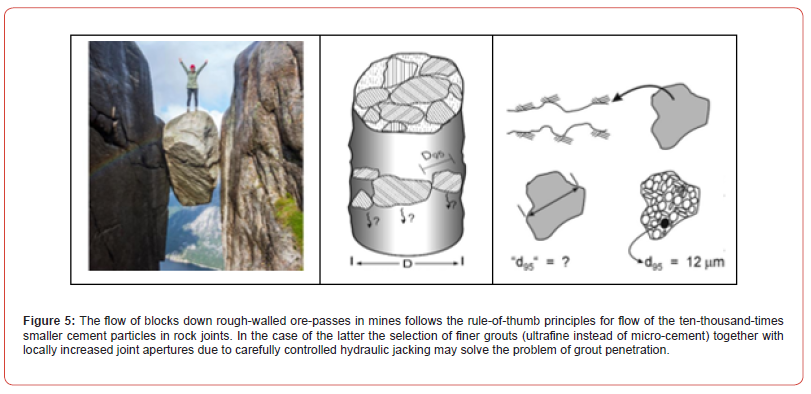
The numerous grouting tests performed in Elkem’s Materials Laboratory twenty years ago included use of the NES apparatus with successively smaller apertures (100, 75, 50μm) until grout mixes with successively reducing water/cement ratios (2.0, 1.3, 1.0, 0.7) were finally experiencing blockage. Just four (4) of the cement manufacturers more than twenty (20) cements were successful in penetrating the 50μm NES ‘smooth fracture’ opening, and these had 10 to 15μm d95 particle sizes, as advertised by their manufacturers. They were therefore demonstrating ‘3 to 5’ times d95 penetrability. In tests at NGI during the extensive UK Nirex project (1990-1996), it was found [10] that 4 x d98 was the mean physical joint aperture that could be grouted. The estimate of aperture was made using the JRC conversion method [11] shown later, utilizing the interpreted hydraulic aperture (e). It was found possible to inject this rock joint (a large-diameter sample of welded tuff from Sellafield) using a stable super-fine grout while the joint was under a normal stress of 3.5MPa. It had a water-flow interpreted hydraulic aperture (e) of 25μm. The grout had a re-checked d98 particle size of 12μm. With JRC = 6, the e = 25μm aperture converts to a mean physical (E) aperture estimate of 47μm. In this case E ≈ 4 x d98. This ‘particlesize’ rule also applies to the orders of magnitude larger ore-passes in mines, with the ‘slow’ particles (in this case blocks) next to the walls defining the very approximate parabolic velocity distribution. Blockage results when the d95 block size causes 4 x d95 to exceed the ore-pass diameter. Table 1 results, from [12] are well-known in the mining industry. Actual explosive ‘bombs’ are rolled down on trolleys to release blockages in the often 5 to 6m diameter orepasses.
Table:1Guidelines for preventing blockage (and the need for ‘bombing’) in ore passes [12].

The Joint Aperture Inequality E > e and its use in Grout Selection
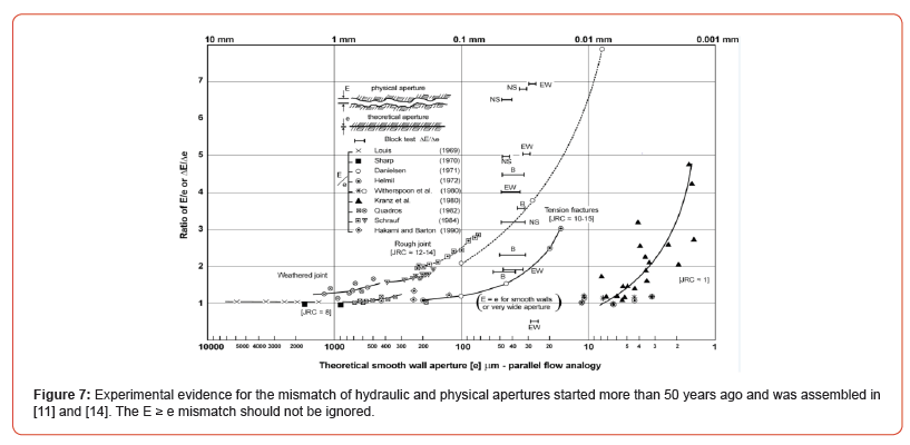
The fundamental mismatch of the mean physical and theoretical hydraulic aperture of joints was already graphed in 1972 [13] and confirmed again following coupled in situ tests in subsequent work in the USA [11]. The aperture E ≥ e (and change of aperture ΔE > Δe) joint flow data was updated by Quadros in [14]. The concept is by now widely accepted following numerous PhD studies. Experience of ΔE > Δe was recorded at the unique 8m3 in situ flat jack loaded block test in 1980-1981, where the mismatch of joint closure and change of hydraulic aperture was confirmed. As must already be clear, the mismatch of the physical groutable aperture (E) and the smaller flow-interpreted hydraulic aperture (e) has an important impact on the optimal size of the chosen micro-cements in the case of high-pressure pre-grouting of tunnels [8]. It was a surprise to find that Swedish grouting designers have apparently focused just on the (non-physical so not actually existing) hydraulic aperture, at their largest project (by length > 2x18km with spans 20-30m): the surprisingly narrow-pillar Stockholm Bypass, as described in [8] (Figures 5,6 and 7).
Filter Pump Testing is Non-Representative of the Penetration of Stable Grouts
Ideal grouts consisting of micro- or ultrafine cement with micro-silica additive to ensure stability and no shrinkage do not take kindly to filter-pump inquisition in an artificial screen taking all the pressure drop. Ideal stable grouts have extensional viscosity that is many times larger than shear viscosity. A desirable grout with lower water/ (cement + filler) ratio gets blocked on the screen, and results [9] in illogical opinions that apertures 8 to 12 times larger than d95 are needed. Stable grouts are rejected.
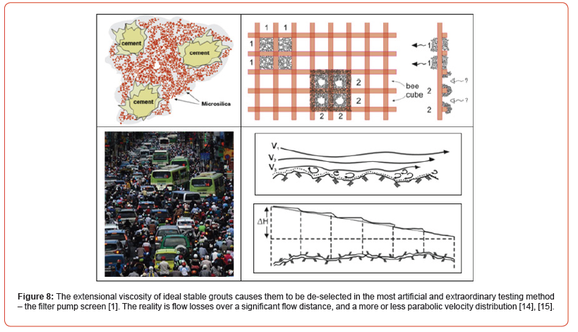
The real situation like the crowded road in Figure 8 is that there are ‘roughness’ losses (slower speed due to parked cars) giving a parabolic-style of velocity distribution, and small pressure losses for grout flowing around interlocking joint-roughness asperities. Widening the road (or local hydraulic joint jacking) gets more grout and traffic further, and if this can occur on intersecting roads even better, but the widening is limited. Anyone who proposes a tollplaza (the filter-pump screen) will cause artificially delayed flows of zero relevance to normal traffic (and grout) flow. The filter-pump screen that symbolizes the traffic plaza delay does not belong in joined rock masses. Imagine a joint aperture of 0.1mm and flow of grout for the desired several meters in each joint intersected. In our analogy the traffic flow equivalent is tens of kilometers. Local hydraulic jacking of the joints (or local addition of new lanes) gives desirable benefits for locally increasing the speed and reach of the grout (and traffic).
High Injection Pressures for Local Joint Widening
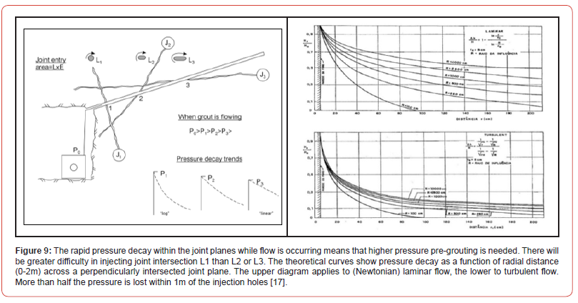
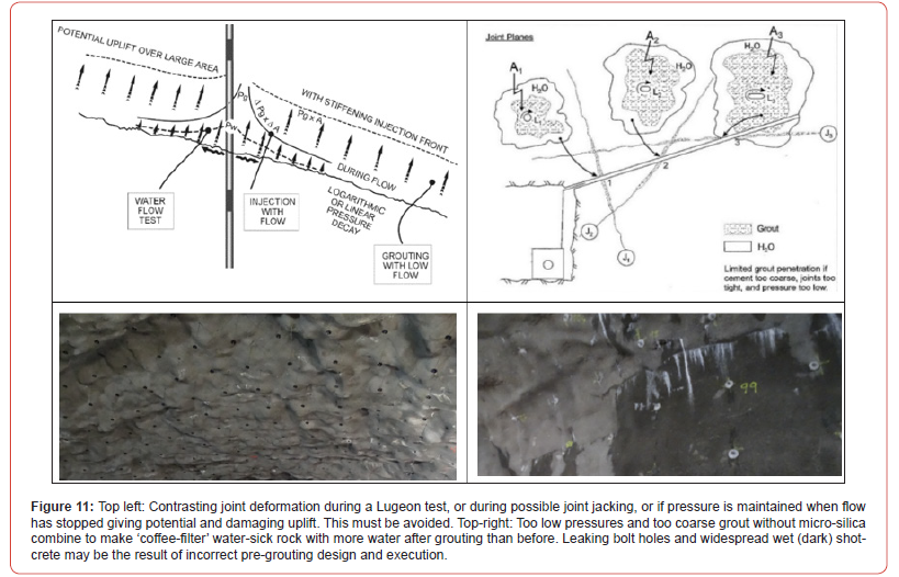
Some 10 to 15 years ago, three rail tunnels west of Oslo, with a total length of 12 km, were all systematically pre-injected, following thorough pre-investigations, and pre-grouting analysis based on specialized core logging. The highest injection pressures used (5 to 10MPa), will have significantly and deliberately exceeded assumed local minimum rock stress, an unfortunate limit suggested in [16] which apparently is still influencing pre-grouting practice in some countries/institutions. It is almost a perfect recipe for injecting only the most permeable joint set. In Norway higher pressures are traditionally chosen to hydraulically jack the joints, but this only occurs in the immediate neighborhood of the injection holes. The radial reduction in pressure, linear to logarithmic, is rapid and very important as it undermines (takes energy from) the action of too low injection pressures. It is indicated in Figure 9.
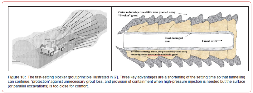
To emphasize the role of pressure-drop-while-flowing the following tunnelling example is illuminating – also illustrating the advantage of a blocker-screen in some cases. See following Figure 10 from [7]. A shallow urban tunnel in phyllite, with 5m of rock cover, was injected at invert level to a final pressure of 6.5MPa, and to 5MPa even in the shallow depth of the arch [6], [18].
However, the establishment of an outer ‘blocker’ screen was necessary for this shallow location. The reality is that while grout is still flowing, deformation in the rock mass is limited to local, nearborehole joint aperture increases, due to the steep pressure decays seen in Figure 9. Without this pressure dissipation mechanism, cases such as the above would obviously be damaging to over-lying rock and soil. Application of such high pressures is discounted in most countries, maybe because of incorrect practice (e.g. seeing the damage that may occur if holding high pressure when flow has stopped?) and failing to appreciate the above flow-dependent pressure decay. This is a real safety valve against unwanted hydraulic fracturing, as opposed to the frequently desirable jacking. In this connection it can be noted that 1 to 5 litres of grout per m3 of rock mass is a typical result for pre-injected tunnels, based on the assumption that a roughly 5 to 6m thick cylinder surrounding the typical 12m span road tunnel is grouted. A rock mass with three perpendicular sets of joints and a mean 1.0mm aperture would take a theoretical 3 litres of grout per m3. An ‘active porosity’ of 0.3% would have been injected in this case. This is far higher than most natural rock mass porosities. In view of the need for stress transfer in a rock mass, and much tighter joints prior to grouting, significant joint jacking must be assumed. Figure 11 illustrates various consequences of high or low grouting pressures..
A Simplified Approach to Pre-Grouting Design – Deriving Mean Physical Joint Apertures
In Figure 12 a suggested ‘workflow’ logic is suggested to enable something more than guesswork, or ‘filter-pump design’ of pre grouting strategies. Appropriately it starts with an analysis of the Lugeon testing, using a simple statistical ‘mean aperture’ approach and simplified ‘cubic network’ assumptions, but flow in only two of three joint sets.
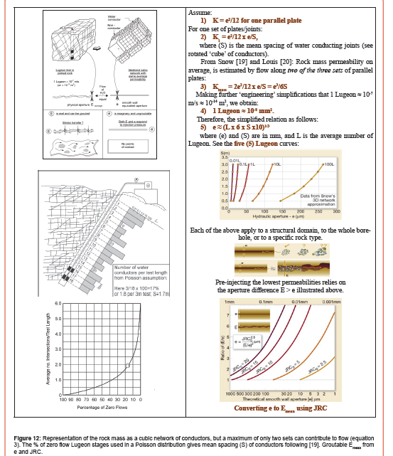
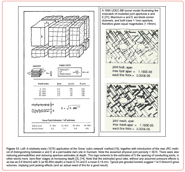
As an example of the proposed method’s application: at the Jong-Asker project’s 2.7 km long Tanum Tunnel, analysis of the systematic permeability measurements, using the methods summarized in Figure 12, indicated tight hydraulic apertures (e) of 25 to 45 μm, but due to the roughness correction (E > e) most physical apertures were estimated to be from 45 to 150 μm. The in-situ rock mass porosities (n ≈ 3E/S: see Figure 13 below) varied from 0.004 (shales) to 0.12 (nodular-limestones) [6].
4. The Jiangdingya slope is in a creep state under the coupling effect of endogenic and exogenic dynamic forces. Precipitation infiltration and agricultural irrigation increase the water content of slope and weaken the shear strength of slope continuously. The water erosion has continuously weakened the stability of the slope, which easily leads to the revival of new large-scale landslide.
Estimating permeability using QH2O
At the Bærum Tunnel shown in Figure 1 the first author was asked to analyse the initially controversial permeability test results obtained in four long (400m) inclined boreholes deliberately set to intersect dominant sub-vertical structure in the folded shales, nodular limestones and numerous sub-vertical igneous dykes. The assessment included extensive shallow seismic refraction measurements, and detailed Q-parameter histogram logging of all the core from the five boreholes BH1 to BH5, a total 1,460m of core. Measured Lugeon values varied from 0.1 to 394, the highest values in the numerous igneous dykes. Figure 14 illustrates the method of permeability prediction that was developed in 2006 – an empirical development made directly from these quality controlled (partly repeated) Lugeon tests.
Key conclusions
1. Good pre-injection results are possible with appropriate
grouts and additives, appropriate pressures, and appropriate
control routines to prevent hydraulic fracturing but allow local
joint jacking if needed due to tight but leaking joints. Start
with higher w/c ratios and reduce to build pressure. Reduce
pressure when flow stops to prevent hydraulic fracturing over
a wider area.
2. The typical range of grouting quantities used in preinjected
tunnels in Norway range from 1 to 5 litres/m3
assuming that on average a 5m thick ‘cylinder’ of surrounding
rock is injected. This suggests that a degree of joint jacking is
occurring and is needed due to too low mass porosity.
3. Due to the rapid drop in pressure in the first 1 meter from
each injection hole that intersects joint planes, it is imperative
to use significant injection pressures in hard rock with tight
joints, even up to 5 to 10MPa. Limiting pressures to ‘minimum
rock stresses’ [16], or to the level of ‘confining stresses’ (recent
SINTEF), to prevent jacking may cause environmental damage.
4. Only one joint set may be injected when pressure is limited
and if the apertures are too small but still conduct water. This
phenomenon has been seen in many tunnelling locations.
5. When rock masses are permeable or weaker, lower
injection pressures are of course sufficient.
6. Three-dimensional permeability measurements in
multiple holes before and after grouting have shown both
rotation and magnitude reduction of permeability tensors as
each set is grouted [22].
7. Grouts can be chosen (ultrafine, micro, industrial) based
on Lugeon and core logging methods as outlined in this paper.
Micro-silica additives are needed to ensure stable non-shrinking
grouts, and one injection cycle. Several injection cycles to
achieve required tightness indicates incorrect technique and/
or incorrect materials and has obvious consequences for
tunnelling cost and time.
8. It is strongly advised never to use the filter pump to test
potential grout mixes. The artificial screens disqualify the best
grouts, as these have marked extensional viscosity. Except for
flowing through sand fillings, the filter pump has no practical
similarity to grout flowing in fractures.
9. In the case of pre-grouting ahead of shallow tunnels it may
be necessary to use a blocker grout that sets fast and provides
confinement for the following higher-pressure pre-injection.
10. When there is a strict demand of maximum inflows in the
range 1 to 3 litres/min/100m one should start with ‘too many
holes’ (especially if large spans) and use the finest cement
and micro-silica. One can then optimize, perhaps reducing the
number of holes, and even use coarser cement if the necessary
results are being readily achieved and documented. All holes
must be injected. Do not start with widely spaced holes in an
effort to reduce costs.
11. Install up-to-the-face shotcrete support and bolt
reinforcement especially if a parallel tunnel is to come (too)
close. Large motorway tunnels should be separated by a pillar
width appropriate to the general rock mass quality, with
conservatism when both tubes need pre-injection.
12. Groundwater drawdown may be ‘doubled’ by twin-tubes:
extra pre-grouting effort should be expected in each tunnel.
In the case of overlying clay only the best possible results will
suffice.
Acknowledgment
Opportunities to visit many tunnels.
Conflict of Interest
No conflict of interest.
References
- Roald S, Saasen A (2004) Penetration of various cement-based injection materials in rock.
- Barton N (2007) Future directions for rock mass classification and characterization-Towards a cross-disciplinary approach Invited lecture. Proc. of 1st US-Canada Rock Mech. Symp. pp.179-188.
- Barton N (2013) TBM prognoses for open-gripper and double-shield machines; challenges and solutions for weakness zones and water. pp.21.1-21.17
- Macias J, Barton N (2022) The NTNU and QTBM methods of prognosis with emphasis on hard-rock mixed-face problems. Pp.35.1-35.31
- Barton N, Buen B, Roald S (2002) Strengthening the case for grouting Tunnels and Tunnelling International. pp.34-36 Dec 2001 and pp 37-39.
- Barton N (2003) Theoretical and empirical understanding of pre-injection and the possibility of reduced amounts of support in selected lengths of tunnel. 29: 140.
- Roald S, Nomeland T, TS Hansen (2002) Multi-Grout – a cement-based injection system.
- Creütz M, F Osterman (2019) The Stockholm Bypass – Design and execution of grouting works Pre-excavation grouting by means of rock fissure grouting with cementitious grouts Geomechanics and Tunnelling, 12(2): 147-157.
- Dalmalm T, Janson T (2001) Grouting field investigation at South Link Proc. of 4th Nordic Rock Grouting Symposium.
- Bhasin R, Johansen PM, Barton N, Makurat A (2002) Rock joint sealing experiments using an ultrafine cement grout Proc. N. American Tunnelling Conf.
- Barton N, Bandis S, Bakhtar K (1985) Strength, deformation and conductivity coupling of rock joints Int. J. Rock Mech Min Sci Geomech Abstr 22(3): 121-140
- Hambley DF, Pariseau WG, Singh MM (1983) Guidelines for open pit orepass design Report prepared for the US Bureau of Mines Washington DC.
- Barton N (1972) A model study of air transport from underground openings situated below groundwater level Proc. of Int. Soc. Rock Mech. Symp. Percolation Through Fissured Rock Stuttgart Theme 3A, p.20.
- Barton N, Quadros E (1997) Joint aperture and roughness in the prediction of flow and groutability of rock masses Proc. of NY Rocks ’97 editor Kim K Linking Science to Rock Engineering. Int J Rock Mech Min Sci 34 (3-4): 907-916.
- Barton N, E Quadros (2019) Understanding the need for pre-injection from permeability measurements: what is the connection? J Rock Mech & Geotech Eng 11(3): 576-597.
- Gustafson G, H Stille (1996) Prediction of groutability from grout properties and hydrogeological data Tunnelling and Underground Space Technology 11(3): 325-332.
- Cruz PT, Quadros EF, Correa Filho D (1982) Evaluation of opening and hydraulic conductivity of rock discontinuities Proc 23rd USA Symposium on Rock Mechanics 1: 69-77.
- Klüver GH, Kveen A (2004) Injection of rock in practice Appendix N Barton Theoretical and empirical understanding of pre-injection (in Norwegian) p.63.
- Snow DT (1968) Rock fracture spacings, openings and porosities. J of Soil Mech and Found Div Proc of ASCE, SMI pp.73-91.
- Louis C (1969) Étude des écolements d’éau dans les fissures et de leur influence sur la stabilité des massifs rocheurs BRGM. Bulletin de la Direction des Études et Ré Serie A 3: 5-132.
- Makurat A, Barton N (1988) Rock mechanical computation of deformations and joint apertures during excavation of the Fjellinjen tunnels pp.27.1-27.27.
- Quadros E, Correa Filho D (1995) Grouting efficiency using directional (3-D) hydraulic tests in Pirapora Dam, Brazil Proc. of 8th ISRM Cong. Tokyo, editor Fujii, Balkema pp.823- 826.
-
Nick Barton* and Steinar Roald. Pre-Grouting for Tunnels in Jointed Rock. Cur Trends Civil & Struct Eng. 10(1): 2023. CTCSE.MS.ID.000726.
-
Pre-grouting, Settlement-damage, High-pressure, Micro-silica, Joint-apertures
-

This work is licensed under a Creative Commons Attribution-NonCommercial 4.0 International License.
- Abstract
- Introduction
- Natural Geological Structure
- Evolution History of Landslide
- Development Characteristics of Jiangdingya Landslide
- Analysis of Catastrophe Mechanism of Landslides
- Stability Analysis of Landslide
- Safety Treatment of Landslide
- Conclusion
- Acknowledgement
- Conflicts of Interest
- References


