 Review Article
Negative Experience of Geotechnical Calculations and Installation of Retaining Buried Structures
Sokolov Nikolay Sergeevich*
Head of the Department of Construction Technologies, Geotechnics and Economics of Construction, I.N. Ulyanov Chuv SU, Director of LLC NPF FORST, Ph.D.,Associate Professor, Member of ROMMGiF and ISSMGE, Cheboksary, Russia
Sokolov Sergey Nikolaevich, Head of the Department of Construction Technologies, Geotechnics and Economics of Construction, I.N. Ulyanov Chuv SU, Director of LLC NPF FORST, Ph.D., Associate Professor, Member of ROMMGiF and ISSMGE, Cheboksary, Russia
Received Date:January 30, 2024; Published Date:February 20, 2024
Abstract
The problem of increasing the load-bearing capacity of foundations is always an urgent problem in modern geotechnical construction. It is of particular importance when building on landslide-prone slopes. At the same time, both designers and customers make irreparable mistakes in the development of design documentation for retaining buried structures during the construction of facilities in such areas. All the allowed flaws are mainly due to the lack of proper control by the technical customer for the performance of pre-design work, including engineering and geological surveys. This article describes a negative case from the geotechnical practice of designing and building a residential complex on a landslide slope. The article is a review.
Keywords:Retaining buried structures; geotechnical construction; electric discharge technology ERT; bored injection pile ERT; unstable slopes; soil anchors ERT
Introduction
Construction of facilities on unstable slopes [1-10] is a complex engineering and geotechnical task associated with ensuring the stability of the entire slope, as well as trouble-free operation of existing buildings, as well as buildings and structures of new construction. It should be noted that the fundamental regulatory document in geotechnical construction is the set of rules SP 22.13330.2016 Updated edition of SNiP 2.02.01-83* “Foundations of buildings and structures”. According to this document, all positions asserting the need to ensure the safe operation of 1) existing buildings, 2) newly erected buildings and structures must be satisfied. In the case of capital construction on slopes, the set of rules SP 22.13330.2016 additionally requires to ensure the stability of the slope with all existing and additionally applied external loads on it. The article discusses a case from the geotechnical practice of designing and constructing buried retaining structures during the construction of a residential area on a landslide slope.
In the developed detailed design for the installation of buried
retaining building structures, there are many items that guarantee
the provision of normative operation of the objects of newly erected
and existing buildings, as well as the slope itself of mandatory
positions, due to the absence of
a. Geotechnical calculations of slope stability according to
engineering and geological sections developed in advance by
the Chief Engineer and approved by the technical customer,
starting from the plateau to the floodplain.
Notes to pos.1.
i. Due to the absence of boreholes in the terms of reference
for surveys at the design engineering and geological sections,
there are no boreholes and no information about engineering
and geological strata throughout the territory of the built-up
slope;
ii. Engineering-geological sections are available only along
the roads (upper and lower streets);
b. Geotechnical calculations carried out by the design
institute are local and do not take into account the whole
variety of factors that guarantee the reliability of the operation
of both the slope and the objects of existing development, as
well as new construction.
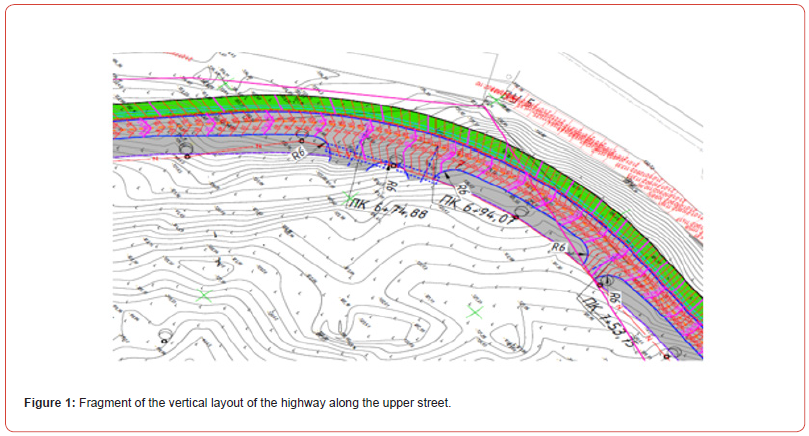
Based on the above, a logical conclusion suggests itself that the design organization should approach such a geotechnical problem more responsibly. Therefore, it is necessary to carefully revise the design documentation for the retaining buried building structures, taking into account the above comments. Below is a brief summary of the design solutions of the developed retaining wall structures. In the basic working design of the installation of retaining structures to ensure the integrity of the roadbed and the integrity of the designed road, the project provides for the installation of retaining walls. The length of the retaining walls is as follows: on the upper street (VU) Uch1-29 - 914.2 m, on the lower street (NU) Uch1-17 - 749.4 m, in the recreation area (ZO) Uch1-9 - 300.2 m. All retaining walls are arranged in plan on curves of different radii (see Figure 1). The maximum height of the retaining walls from the road marks is 11.0 m. Reinforced concrete retaining walls of the Upper Street are made of bored piles made of concrete B30 F200 W6, diameter ø800.0-1000.0 mm, united by a monolithic reinforced concrete grillage with dimensions of 0.5x1.2x6.6 m made of concrete B30 F300 W8. Retaining walls in sections 5-7, 9-11, 13-26 should be installed in casing pipes with a diameter of ø1020.0 mm with a wall thickness of t=14.0 mm (casing pipes are not removed!), between all bored piles in these areas, ground anchors of piles with a rod made of tubular screw rods “Titan” or analogues are arranged. On the side of the road, vertical drainage is arranged between all the drill pillars. Holes are drilled in the drill poles and reinforcement anchors are glued. Flat reinforcement meshes are installed, and expansion joints and drainage devices are arranged. The wall is lined with a reinforced concrete panel with a thickness of t=200.0 mm (B30).

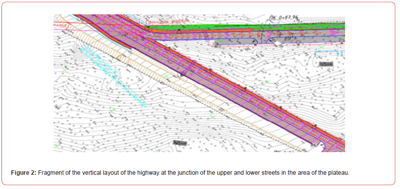
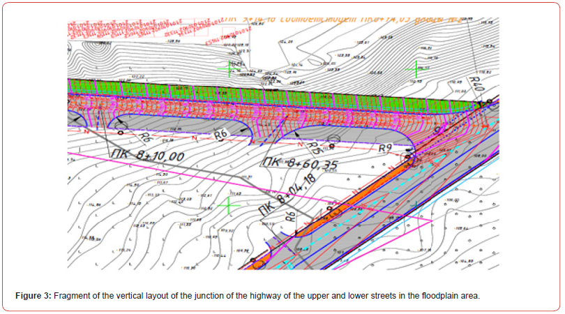
Reinforced concrete retaining walls of the Lower Street and recreation area are made of bored piles made of concrete B30 F200 W6, diameter ø800.0-1000.0 mm, united by a monolithic grillage measuring 0.5x1.2x6.6 m made of concrete B30 F300 W8 (see Figures 2 & 3). Backfilling of retaining walls along the entire length is carried out with soil with an angle of internal friction φ at least 35° with layer-by-layer compaction up to Buy=0.98. On the side of the road, vertical drainage is arranged between all the drill pillars. Holes are drilled in the drill poles and reinforcement anchors are glued. Reinforcement meshes are installed, and expansion joints and drainage devices are arranged. The wall is lined with a reinforced concrete panel with a thickness of t=200.0 mm (B30). Filtration (drainage) water is drained through drainage pipes with a diameter of 80.0 mm, located in a crushed stone prism wrapped with geotextile material “KANVALAN MF 25” with a density of 500.0 g/m2 (or equivalent). To protect the front side of the surface of the retaining wall from storm water leaks, it is necessary to provide a canopy with a “teardrop”.


It should be noted that the developed project of buried retention structures turned out to be technically inexpedient and, most importantly, economically inefficient. In this regard, the customer was forced to consider an alternative option. The proposal put forward by us for the design and installation according to technical and economic indicators was approved by the customer. At the same time, the use of bored injection piles arranged using electric discharge technologies (bored injection piles ERT) as an alternative to such structures made it possible to save several times.
References
- Ilichev VA, Mangushev RA, Nikiforova NS (2012) Experience of development of Russian megacities underground save. Foundations, foundations and soil mechanics (2): 17-20.
- Ulickij VM, Shashkin AG, Shashkin KG (2010) Geotechnical support for urban development South Geotechnical Support of Urban Development. Saint Petersburg: Georeconstruction pp. 551.
- Ilichev VA, Konovalov PA, Nikiforova NS, Bulgakov LA (2004) Deformations of the Retaining Structures Upon Deep Excavations in Moscow. Proc. Of Fifth Int. Conf on Case Histories in Geotechnical Engineering, New York, USA pp. 5-24.
- Ilichev VA, Nikiforova NS, Koreneva EB (2007) Computing the evaluation of deformations of the buildings located near deep foundation tranches. Proc. of the XVIth European conf. on soil mechanics and geotechnical engineering. Madrid, Spain, «Geo-technical Engineering in urban Environments» 2: 581-585.
- Nikiforova NS, Vnukov DA (2011) Geotechnical cut-off diaphragms for built-up area protection in urban underground development. The pros, of the 7thI nt. Symp. «Geotechnical aspects of underground construction in soft ground», tc28 IS Roma, AGI, pp. 157NIK.
- Nikiforova NS, Vnukov DA (2004) The use of cut off of different types as a protection measure for existing buildings at the nearby underground pipeline’s installation. Proc. of Int. Geotech. Conf. dedicated to the Year of Russia in Kazakhstan. Almaty, Kazakhstan, pp. 338-342.
- Petrukhin VP, Shuljatjev OA, Mozgacheva OA (2003) Effect of geotechnical work on settlement of surrounding buildings at underground construction. Proceedings of the 13th European Conference on Soil Mechanics and Geotechnical Engineering. Prague.
- Sokolov NS, Viktorova SS (2018) Method of Aligning the Lurches of Objects with Large-Sized Foundations and Increased Loads on Them //Periodico Tche Quimica T. 15. Special Issue 1. C.1-11.
- Sokolov NS, Petrov MV, Ivanov VA (2014) Problemy rascheta boroinjectionnykh pile, izproizvodstvennykh s ispol'zovaniem dischargeno-impulsionnoy tekhnologii [Problems of calculation of bored piles, manufactured with the use of discharge-impulse technology]. Proceedings of the VIII All-Russian (II International) Conference. Editorial Board: N.S. Sokolov (Editor-in-Chief), D.L. Kuzmin (Responsible Secretary), AN Plotnikov, LA Sakmarova, AG Lukin, VF Bogdanov, VI Tarasov pp. 415-420.
- Sokolov NS, Sokolov AN, Sokolov SN, Glushkov VE, Glushkov AV (2017) Calculation of boroinjection pilea EPT of higher nasal ability yu Calculation of bored injection vacuum of EPT of increased baring capacity (11): 20-25.
-
Sokolov Nikolay Sergeevich*. Negative Experience of Geotechnical Calculations and Installation of Retaining Buried Structures. Cur Trends Civil & Struct Eng. 10(3): 2024. CTCSE.MS.ID.000738.
-
Retaining buried structures; geotechnical construction; electric discharge technology ERT; bored injection pile ERT; unstable slopes; soil anchors ERT; Iris Publishers, Iris Indexing Sites
-

This work is licensed under a Creative Commons Attribution-NonCommercial 4.0 International License.


