 Review Article
Geotechnical Practice of Construction on Unstable Slopes
Sokolov Sergey Nikolaevich*
Head of the Department of Construction Technologies, Geotechnics and Economics of Construction, I.N. Ulyanov Chuv SU, Director of LLC NPF FORST, Ph.D.,Associate Professor, Member of ROMMGiF and ISSMGE, Cheboksary, Russia
Sokolov Sergey Nikolaevich, Head of the Department of Construction Technologies, Geotechnics and Economics of Construction, I.N. Ulyanov Chuv SU, Director of LLC NPF FORST, Ph.D., Associate Professor, Member of ROMMGiF and ISSMGE, Cheboksary, Russia
Received Date:May 01, 2024; Published Date:May 20, 2024
Abstract
The construction of facilities for various purposes in rough areas in cramped conditions of urban development is the main problem for builders related to the solution of geotechnical problems of ensuring both the slope itself and buildings and structures of the surrounding buildings in the zone of geotechnical influence. Questions arise with the need to develop buried retention structures. The article discusses a case from the geotechnical practice of installing retention structures with the use of bored piles with diameters of 600 mm and 800 mm and ground anchors arranged using electric discharge technology (ERT anchors).
Keywords:Geotechnical construction; electro hydraulics; monolithic reinforced concrete grillage; bored piles; especially cramped geotechnical conditions; soil anchors of ERT
Introduction
Construction of buried objects in particularly cramped
conditions on unstable slopes from geotechnical engineers [1-7]
of a specific approach, who must show ingenuity and ingenuity in
the use of modern geotechnical technologies that ensure the safe
operation of existing buildings [8-10] both during construction
and during the operation of newly erected buildings and structures
[11-15]. The initial data for the development of the project for the
installation of retaining structures were:
a. Project documentation “Integrated development
of the residential complex “Dubrava Park”, the city of
Cheboksary” (financing the costs of engineering networks and
communications for water supply, sewerage, electricity and
heat supply, gas supply, roads for the complex development of
the residential complex “Dubrava Park”, the city of Cheboksary).
Street and road networks of the Dubrava Park micro district,
Cheboksary” code of the Group of Companies No. 24/10-2022,
made by LLC “CITYSTREETPROJECT” in 2023;
b. Technical report on the results of engineering and
geological surveys at the facility: “Land plot with cadastral
number 21:01:010902:156, located at: Chuvash Republic -
Chuvashia, Cheboksary urban district, Cheboksary”, made by
GIZ LLC in 2021, code 10309-IGI;
c. Determination of the stability of the retaining walls of
the complex development of the Dubrava Park micro district
in Cheboksary. Technical report on the results of engineering
and geological surveys for the preparation of project
documentation, code 5570-IGI, performed by CJSC “Institute
“Chuvashgiprovodkhoz” in 2023;
d. Technical report “Examination of the technical condition
of the building structures of the garage complex and residential
building No. 25 k.1 at the address A. Mittov Boulevard, falling
into the zone of influence of the new construction of the object
“Residential complex “Dubrava”, code TO-09/23, performed by
LLC “IC “EXPERT” in 2023 [16-19].
Geomorphologically, three areas have been identified on the construction site: 1) the marginal part of the drive-dividing plateau (types AI and AII) with elevations from 130.0 to 140.0 m, with a slight slope (up to 4-5º) to the SE, to the Sugutka valley, and it consists of up to six geomorphological elements: at least three fragments of leveling surfaces with accumulative (AI) and denudation (AII) areas and two buried gullies with ravines and drainage hollows within them; 2) floodplain accumulative (PT) terrace with a width of 2.0-3.0 m to 15.0-20.0 m and a narrow channel of the Sugutka River with elevations from 104 m to 98 m, the average slope of the floodplain is 0.006; 3) landslide (BIV-BV) left slope of the valley between the plateau and the floodplain of the Sugutka River. It is gently sloping, wavy-bumpy with many winding hollows of runoff on the borders of more than two dozen local landslides of flow and slippage with head blocks Vr, Sb.
Within the erosion cut marks, the bedrock is represented by essentially terrigenous (argillitized clays and sands) rocks of the Vyatka and Severodvinsk horizons of the Tatar stage of the Upper Permian (P3t) with a marking pack of marls “Zh” between them at elevations of 120.0-125.0 m (the South East area) and 114.0- 11.0 m (the SevOS site). Their subhorizontal occurrence without signs of deformation indicates the general stability of slopes with a steepness of less than 10º and a height of up to 36 m. Most of the territory is covered from the surface with a soil and vegetation layer (PRS) with a thickness of 0.2-0.5 m. on the slope there are the same rocks, but fragments of the 1st (Ostashkov-aIII2) and 3rd (Moscow-aII2) alluvial-periglacial terraces deformed by landslides; on the floodplain there are alluvial loams (aIV) that are silty to varying degrees. Of all the soils of the Quaternary age, the greatest role in the stability of the massif is played by the soils EWG-1 (IGE Nos. 3, 4) and EWG-2 (IGE Nos. 5, 6).
Groundwater is represented by four aquifers (aquifers). The first aquifer has a high-water regime within the built-up part of the plateau. The second aquifer is an interstitial aquifer in a pack of marls of the bedrock massif in the range of 121.0-124.0 m in the southern part of the massif and 114.0-110.0 m in the northern part. The third aquifer is a slope complex that includes the PV of all three floodplain and four or five landslide terraces with a total thickness of up to 10.0 m on the aquiclude represented by the surface of the Tatar bedrock. The 4th VG is represented by the PV of the floodplain terrace of the Sugutka River, which is closely connected with channel waters. Of these, the 2nd and 2nd VG play the greatest role in the stability of the slopes. In terms of chemical composition, PVs are fresh, bicarbonate, calcium, non-aggressive to concrete of the W4 grade. For approximate calculations, the following Kf values are recommended: for loess loams – 0.64 m/day, for sandy loams (dQII) – 1.05 m/day, for fractured bedrock clays (P3t) – 0.71 m/day.
Structural solutions of buried reinforced concrete retaining
structures, substantiated on the basis of geotechnical stability
calculations taking into account design loads, are:
a) The upper retaining wall (buried reinforced concrete
retaining structure) is a flexible anchored wall. The structure
of the fence is made of bored piles, fixed from horizontal
displacement by ground anchors, arranged using electric
discharge technology (ERT anchors). At the top, the piles are
united by a monolithic reinforced concrete binding beam. The
cladding of the vertical surfaces of the buried structure is made
in a monolithic reinforced concrete design. Bored piles are
designed with diameters of 620 mm and 800 mm, lengths of
20.0 m, 18.0 m, 17.0 m and 12.0 m. The length of the root of
the ERT ground anchors is 10.0 m. Vertical drainage is provided
behind the lining in the interpile space, which ensures the
drainage of groundwater accumulated behind the wall into
the drainage collector located along the retaining wall. Surface
water drainage is carried out through reinforced concrete
flumes located along the strapping beam.
b) The lower retaining wall (buried reinforced concrete
retaining structure) is a complex consisting of anchor
structures, an angle reinforced concrete wall and a pile
foundation. Fencing piles are bored with a diameter of 620
mm, 13.0 m and 19.0 m long, are made under the protection of
casing pipes. Ground anchors (ERT anchors) with a diameter
of 150 mm (diameter according to the drilling tool), root
length - 10.0 m, are made using electric discharge technology
and prestressed For Reservoir drainage is provided to ensure
the passage of groundwater at the level of the slab part (only
in areas with a pile foundation). A drainage collector ensures
the passage of groundwater from the level of the wall part of
the support. Surface water drainage is carried out through
reinforced concrete flumes located along the retaining wall.
Calculations on the strength of the base of retaining walls were carried out in the Geo Wall software package based on the Blum-Lohmeyer method (the “elastic line” method) and the Jacobi method (iterative process).
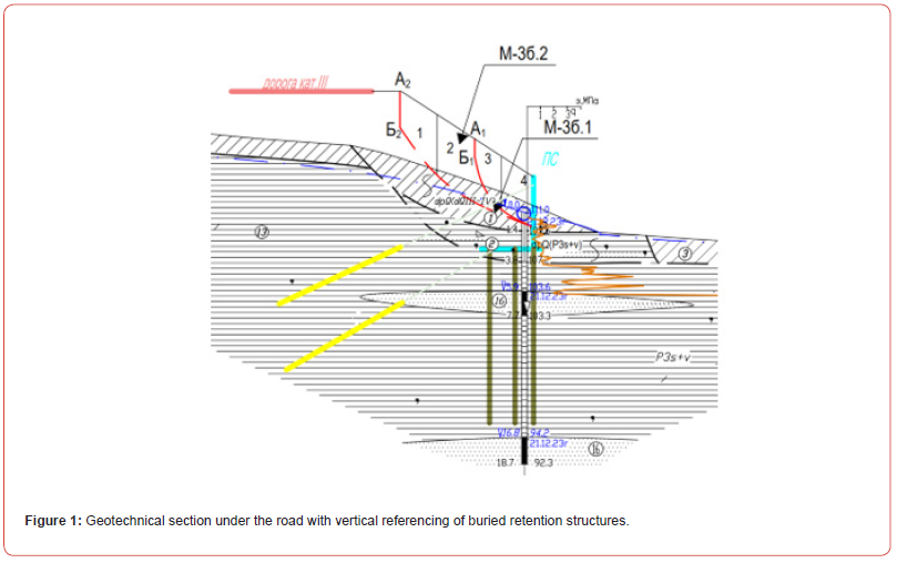
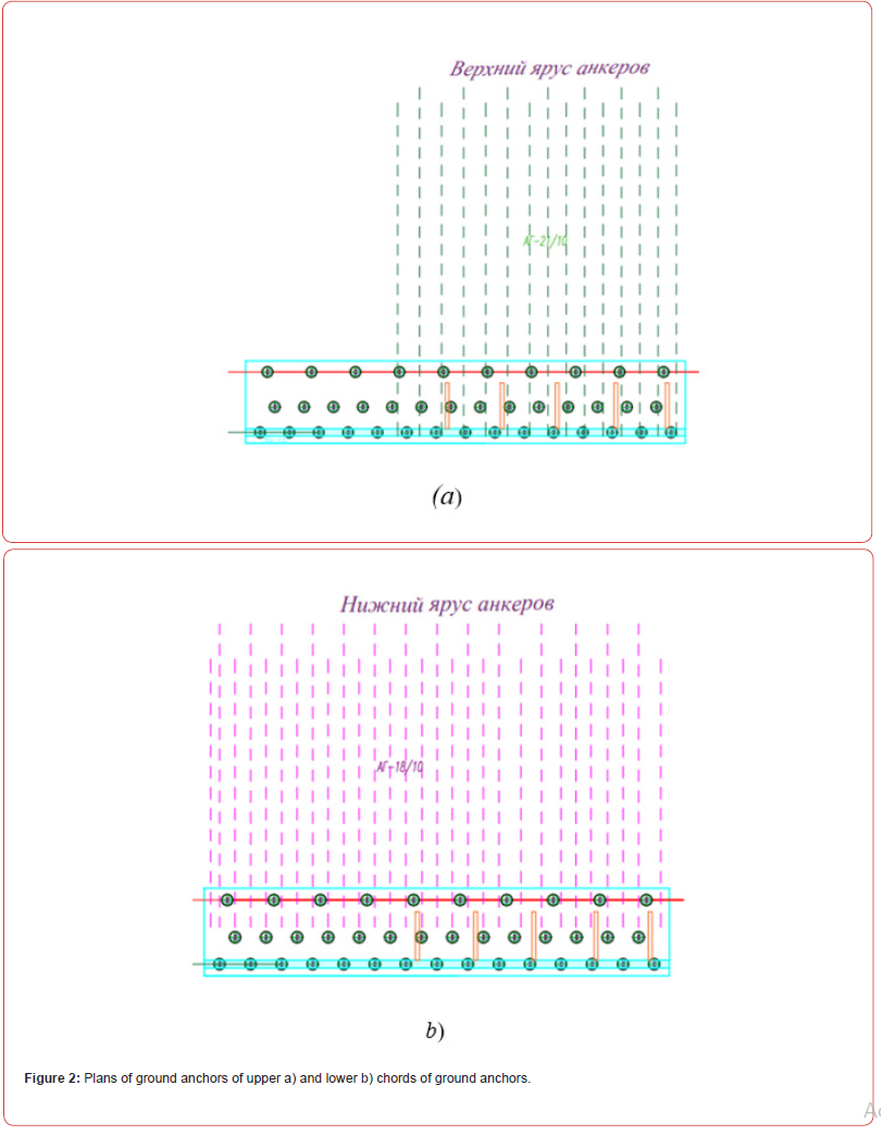
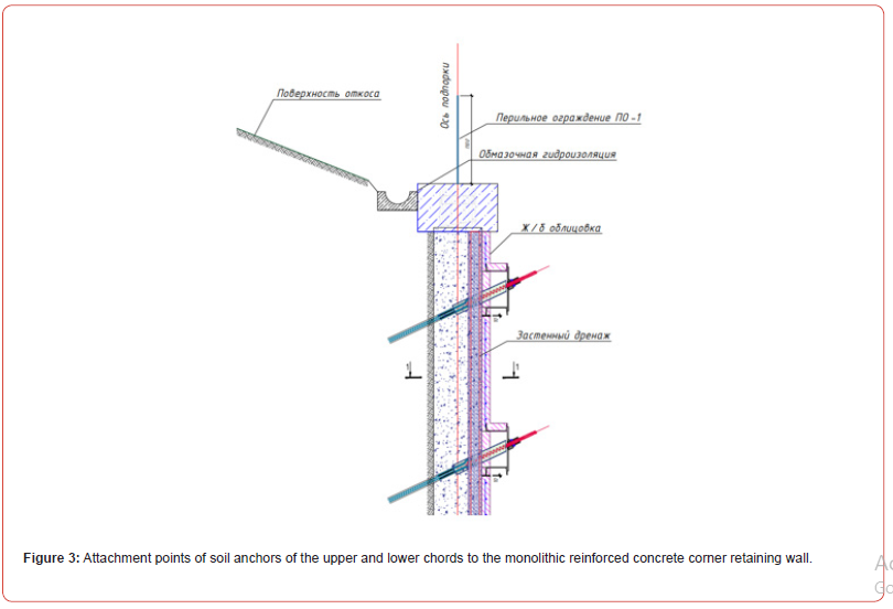
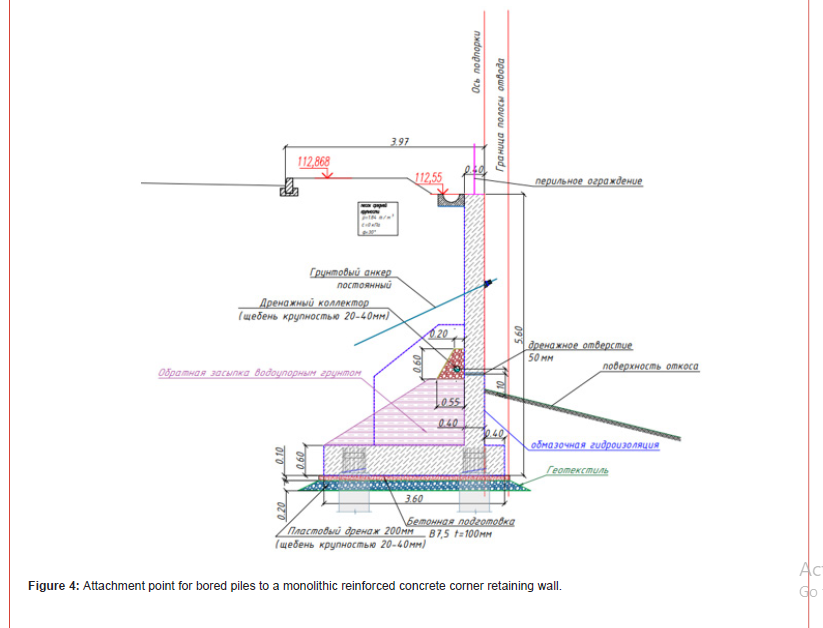
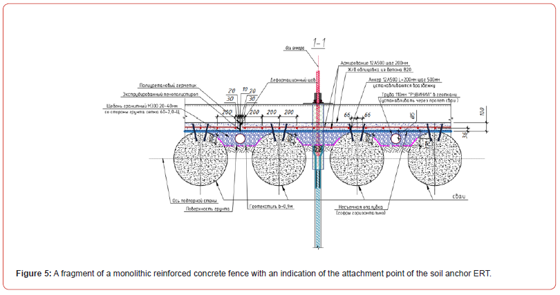
Figures 1-5 shows an engineering-geological section under the road with vertical referencing of buried retaining structures, plans of soil anchors of the upper a) and lower b) chords of the ground anchors, attachment points of the soil anchors of the upper and lower chords to the monolithic reinforced concrete corner retaining wall, the attachment point of bored piles to the monolithic reinforced concrete corner retaining wall, a fragment of the monolithic installation of the monolithic reinforced concrete fence with an indication of the attachment point of the ground anchor ERT.
References
- Ter-Martirosian AZ., Kivluik VP, Isaev IO, Shishkina VV (2022) Analysis of the calculated prerequisites for the geotechnical forecast of new construction on the surrounding buildings. Zhilishchnoe Stroitel’stvo [Housing Construction] 9: 57-66.
- Mangushev RA, Nikiforova NS (2017) Technological precipitation of buildings and structures in the zone of influence of underground construction. Moscow, ASV Publ pp. 168
- Ilichev VA, Konovalov PA, Nikiforova NS, Bulgakov LA (2004) Deformations of the retaining structures upon deep excavations in Moscow. Proc. Of Fifth Int. Conf on Case Histories in Geotechnical Engineering. New York, USA pp. 5-24.
- Sokolov N, Ezhov S, Ezhova S (2017) Preserving the natural landscape on the construction site for sustainable ecosystem. Journal of applied engineering science 15(4): 518-523.
- Nikiforova NS, Vnukov DA (2011) Geotechnical cut-off diaphragms for built-up area protection in urban underground development. The pros, of the 7thI nt. Symp. «Geotechnical aspects of underground construction in soft ground. tc28 IS Roma, AGI, , 157NIK.
- Nikiforova NS, Vnukov DA (2004) The use of cut off of different types as a protection measure for existing buildings at the nearby underground pipelines installation. Proc. of Int. Geotech. Conf. dedicated to the Year of Russia in Kazakhstan. Almaty, Kazakhstan pp. 338-342.
- Petrukhin VP, Shuljatjev OA, Mozgacheva OA (2003) Effect of geotechnical work on settlement of surrounding buildings at underground construction. Proceedings of the 13th European Conference on Soil Mechanics and Geotechnical Engineering. Prague.
- Sokolov NS (2016) Technological methods of boring injection piles with multi-place widenings. (10): 54-57.
- Sokolov NS (2019) Technology of increasing a base bearing capacity. Stroitel’nye Materialy [Construction Materials] 6: 67-72.
- Sokolov NS, Sokolov AN, Sokolov SN, Glushkov VE, Glushkov AV (2017) Calculation of bored injection piles of ERT of increased bearing capacity. 11: 20-25.
- Sokolov NS, Sokolov AN, Sokolov SN, Glushkov VE, Glushkov AV (2017) Calculation of flight augering piles of high bearing capacity. Zhilishchnoe Stroitel’stvo [Housing Construction] 11: 20-25.
- Nikonorova IV, Sokolov NS (2017) Construction and territorial development of the landslide slopes of the Cheboksary reservoir. 9: 13-19.
- Sokolov NS, Sokolov SN, Sokolov AN (2023) Technology of the Monolith Reinforced Concrete Rostwerk in Confined Conditions of a Functioning Object. 7: 12-16.
- Sokolov NS, Sokolov SN, Sokolov AN (2023) The practice of construction in particularly cramped conditions. Zhilishchnoe Stroitel’stvo [Housing Construction] 9: 41-47.
- Sokolov NS, Sokolov SN, Sokolov AN (2023) Geotechnical technology of construction of engineering structures. 11: 52-55.
- Sokolov NS, Viktorova SS, Fedorova TG (2014) Novoe v arkhitekture, proektirovanii stroitel'nykh konstruktsii i rekonstruktsiya : Materialy VIII Vserossiyskoy (II Mezhdunarodnoy) konferentsii, Cheboksary, 20-21 noyabrya 2014 goda / Editorial board: N.S. Sokolov (guest editor), D.L. Kuzmin (responsible secretary), A.N. Plotnikov, L.A. Sakmarova, A.G. Lukin, V.F. Bogdanov, V.I. Tarasov. - Cheboksary: Chuvash State University named after I.N. Ulyanov pp. 411-415.
- Sokolov NS, Petrov MV, Ivanov VA (2014) Novoe v arkhitekture, proektirovaniye stroitel'nykh konstruktsii i rekonstruktsiya: Materialy VIII Vserossiyskoy (II Mezhdunarodnoy) konferentsii, Cheboksary, 20-21 noyabrya 2014 goda [New in architecture, design of construction structures and reconstruction: Materials of the VIII All-Russian (II International) Conference, Cheboksary, 20-21 November 2014] / Editorial Board: N.S. Sokolov (guest editor), D.L. Kuzmin (responsible secretary), A.N. Plotnikov, L.A. Sakmarova, G. Lukin, V.F. Bogdanov, V.I. Tarasov. - Cheboksary: Chuvash State University named after I.N. Ulyanov pp. 415-420.
- Sokolov NN, Sokolov SN, Sokolov AN (2017) Fine-grained concrete as a structural construction material of bored injection piles / ERT N. S. S. Sokolov, S. N. Sokolov, A. N. Sokolov // Stroitel'nye materialy [Construction materials]. 5: 16-19.
- Utility model patent No. 161650 U1 Russian Federation, IPC E02D 5/34, E02D 5/44. Device for camouflage widening of the rammed structure in the ground: No. 2015126316/03: declared. 01.07.2015: publ. 27.04.2016 / N. S. Sokolov, Kh. A. Dzhantimirov, M. V. Kuzmin [et al.]; Applicant: Federal State Budgetary Educational Institution of Higher Professional Education "Chuvash State University named after I.N. Ulyanov".
-
Sokolov Sergey Nikolaevich*. Geotechnical Practice of Construction on Unstable Slopes. Cur Trends Civil & Struct Eng. 11(1): 2024. CTCSE.MS.ID.000751.
-
Geotechnical construction; electro hydraulics; monolithic reinforced concrete grillage; bored piles; especially cramped geotechnical conditions; soil anchors of ERT; Iris Publishers; Iris Publishers Group
-

This work is licensed under a Creative Commons Attribution-NonCommercial 4.0 International License.


