 Research Article
Experimental Data Collection for A Sphere on A Forced Oscillating Track
Justin Arbaiza and David Boyajian*
Department of Civil Engineering and Construction Management, California State University, USA
David Boyajian, Department of Civil Engineering and Construction Management, California State University, Northridge, CA, USA
Received Date:February 16, 2024; Published Date:February 21, 2024
Abstract
This work involves the experimental setup of an oscillating V-shaped trough upon which a steel sphere is subjected to a back and forth rolling motion. The trough is hinged at the center and actuated by a piston that imparts a force near one end of the track, resulting in upwards-&-downwards motion and causing the metal sphere to roll within the V-shaped trough. The real-time data collected involved the position of the sphere relative to the static equilibrium position (SEP) as a function of time as well as other corresponding data, e.g., the angle of the track. It is hoped that this pilot study can be extended to further both theoretical as well as analytical studies of such a dynamical system.
Keywords:Vibrations; Computational Modeling; Multifunctional Structures; Dynamic Loads; Testing
Nomenclature:dsphere: Diameter of sphere
g: Acceleration due to gravity
Ibar: Mass moment of inertia of bar
Isphere: Mass moment of inertia of sphere
lscrew: Distance between each screw on disk
mbar: Mass of bar
msphere: Mass of sphere
rsphere: Radius of sphere
s: Arc length of disk
αbar: Angular acceleration of bar
αdisk: Angular acceleration of disk
αsphere: Angular acceleration of sphere
θ: Angle of the track relative to horizontal
ωbar: Angular velocity of bar
ωdisk: Angular velocity of disk
ωsphere: Angular velocity of sphere
Introduction
Vibrations are very important in many engineering applications. Cars, machines, cellular phones, and a host of many other devices that people have come to rely upon would not be possible without this physical phenomenon. Vibration analysis allows engineers to determine the stability and effectiveness of a mechanical system. This pilot study involved an investigation of a mechanical system to evaluate the displacement and angular frequency of a solid metal sphere rolling on an oscillating V-shaped track. In this vein, an application to better understand this complex behavior can, at a first step, be viewed using the idea of objects rolling down inclined planes at various angles and speeds. It is helpful to look into similar studies that have been conducted in the past. A work that uses control theory through a Partial Integrator Derivative (PID) device to stabilize the ball on the oscillating track is presented by Jadhav et al. (2017) [1]. D’Anna et al. (2021) studied spheres of various radii rolling on tracks where the position was measured experimentally using sensors, with velocity vs. time of the response of the sphere measured as well [2]. Additional works present the results of various spheres rolling on a track at different angles [3- 6]. Track variations were studied by Ladino (2020) using a multislotted aluminum sheet with varying widths and different angles of inclination as the surface upon which the steel sphere rolled [7].
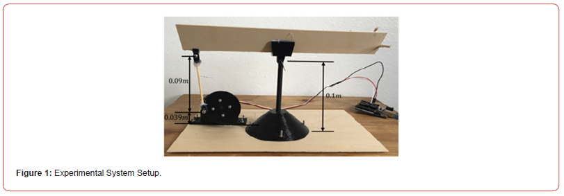
The relevance to this pilot study of a sphere rolling on a forced oscillating track (Figure 1) to the real world and how it matters can be seen, for example, from the rocking up and down of bridge girders on elastomeric bearing pads during a seismic event (Figure 2). The focus in this paper is to experimentally collect the position of the steel sphere as it rolls along the V-shaped oscillating track, a setup that may be considered as a two degree of freedom (2DOF) system. Pedagogically, the system is rife with important concepts of engineering dynamics, e.g., particle and rigid body kinematics and kinetics [8]. The V-shape track was powered by an Arduino microcontroller which sends digital inputs to the servo-mechanism resulting in the external excitation to cause the V-shaped track to oscillate up and down in a see-saw manner (Figure 1). To carry out the experimental investigation, the sphere undergoing its described motion was videotaped and carefully analyzed for its dynamical response.

Materials and Methods
Some of the materials that were used during this research involved 3D printed parts; a conical shaped base that was bolted down using steel screws to a piece of rectangular plywood; the housing for the servomotor which was connected to a flywheel; and the ball in the experiment consisting of a steel sphere of mass 0.005kg and a radius of 0.5cm (Figure 3). Plywood was used to form the V-shaped trough to serve as the track for the sphere to roll back and forth upon. Figure 4(a) shows the Arduino Uno R3 microcontroller that was used to power the mechanical system, and Figure 4(b) displays the S3305 servomotor that was connected to the Arduino Uno to provide the rotation of the flywheel, which, in turn, caused the oscillatory motion of the V-shaped track through a connecting rod (Figure 1).


Results and Discussion
A top view of the experimental system used with a ruler-inset upon the V-shaped track (Figure 5) for ease of measuring the position of the steel sphere with respect to time. In order to collect measurements of the position of the steel sphere, the oscillating system was videotaped and later analyzed by starting and stopping the video at different timestamps to ascertain the position of the ball rolling on the track.
Motion of the Sphere Through its Phases
Figure 6 is a schematic of the experimental setup showing the dimensions as well as the various symbols used in conducting the dynamical and vibrational analysis for this study.
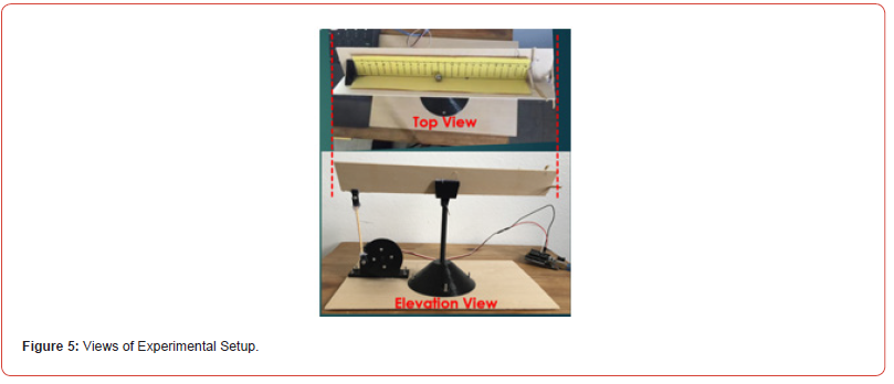
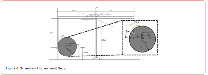
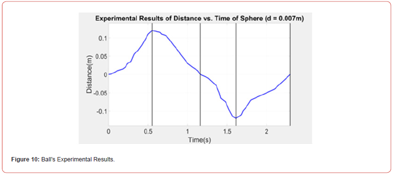
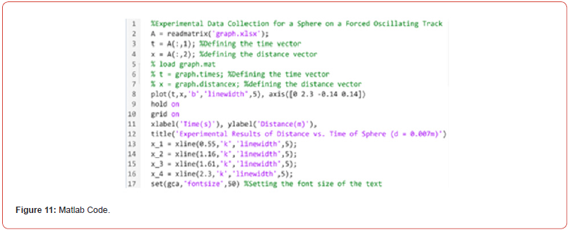
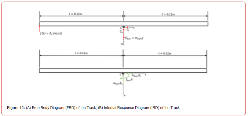
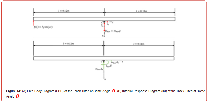
During the experiment, the steel sphere’s location could be characterized by its motion through its different phases. For instance, at time t=0s with the sphere positioned at the static equilibrium position (SEP) and the track in a horizontal position, the ball would begin to roll away from the center as the track begins to tilt constituting the ball in its Phase 1 motion. As the track oscillates and tilts the other way, the ball would begin rolling back towards the SEP in its Phase 2 motion. Thus, the odd numbered Phases (1,3) represent the sphere rolling away from the SEP, whereas, the even numbered Phases (2,4) represent the sphere rolling towards the SEP (Figures 7-9). The experimentally collected data of the sphere’s motion through its different phases is captured and plotted in Figure 10. The actual motion of the sphere rolling through its different phases is shown in Figure 10 as generated using MATLAB with accompanying code shown in Figure 11. Arduino (Figure 12) was used to operate the flywheel that imparted simple harmonic excitation of the V-shaped track through the linkage (Figures 1,13,14).



Conclusion
An experimental oscillating V-shaped track with a steel sphere rolling in its trough, was designed and constructed to perform measurements on the ball’s position with respect to time. The motion was videotaped and used to start and stop the motion at equal intervals of time in order to collect the data. Initially, a servomotor was used to cause rotation of the flywheel that, in turn, resulted in the simple harmonic excitation of the track through a linkage, however, it this motor was found not to adequately cause full rotary (360°) motion, at which point, a stepper motor was resorted to that did solve the issue in a nice, continuous fashion. Future studies will consider an enhanced experimental setup utilizing 3D printed (Tamiya USA) parts outfitted with ultrasonic sensing capabilities for superior distance detection and the collection of measurements. Moreover, numerical and analytical characterizations will be performed to model and corroborate experimental results.
Acknowledgements
The lead author would like to express his gratitude towards the National Science Foundation which provided partial support of this study through Grant # HRD-1826490. He is also grateful to his research advisor Dr. David Boyajian of California State University, Northridge (CSUN) for his guidance and for enabling this research.
Lastly, while trekking on this journey filled with highs and lows and the strains of Covid, the lead author would likewise give a huge word of thanks to his parents, family, and friends (Fernando Barajas, Jocelyn Rodriguez and Estefania Lopez), and to his beloved grandmother, Maria Aurora Espinoza, who would routinely encourage him by saying, “Sigue para-Adelante y no mires para atras. El sol volvera mañana.”
References
- Jadhav VD, Bhapkar DP, Rane MP, Kokate RD (2017) Design and Implementation of Ball and Beam Control System. International Journal of Innovative Research in Science, Engineering and Technology (IJIRSET) 6(5): 9110-9118.
- D’Anna M, Fuchs HU, Corni F (2021) Spheres rolling on an inclined track. Physics Education (Paper ID 055006) 56: 11.
- Hierrezuelo J, Carnero C (1995) Sliding and rolling: the physics of a rolling ball. Phys Ed 30: 177-181.
- Phommarach S, Wattanakasiwich P, Johnston I (2012) Video Analysis of Rolling Cylinders. Physics Education 47: 189-196.
- Aghamohammadi C, Aghamohammadi A (2011) Slipping and rolling on an inclined plane. Eur J Phys IOP Science 32: 1049-1057.
- Cross R (2015) Rolling to a stop down an inclined plane. Eur J Phys (Paper ID 065047), IOP Science 36: 7.
- Ladino LA (2020) Rolling Sphere Along an Inclined Multi-Slotted Track. Physics Education (Paper ID 035001), IOP Science 55: 4.
- Meriam JL, Kraige LG, Bolton JN (2015) Engineering Mechanics Dynamics, Wiley.
-
Justin Arbaiza and David Boyajian*. Experimental Data Collection for A Sphere on A Forced Oscillating Track. Cur Trends Civil & Struct Eng. 10(4): 2024. CTCSE.MS.ID.000742.
-
Vibrations; Computational Modeling; Multifunctional Structures; Dynamic Loads; Testing; Iris Publishers, Iris Indexing Sites
-

This work is licensed under a Creative Commons Attribution-NonCommercial 4.0 International License.


