 Research Article
Evaluation of the Seismic Behavior of Composite Knee Braced Frame
Morteza Naghipour1*, Mobin Mohammadzadeh Rad2 and Arash Sabzi2
1Professor, Department of Civil Engineering, Babol Noshirvani University of Technology, Babol, Mazandaran, Iran
2Graduate student, Department of Civil Engineering, Babol Noshirvani University of Technology, Babol, Mazandaran, Iran
Morteza Naghipour, Professor, Department of Civil Engineering, Babol Noshirvani University of Technology, Babol, Mazandaran, Iran
Received Date:January 08, 2024; Published Date:January 30, 2024
Abstract
Composite moment frames are systems which consist of concrete-filled steel tube (CFT) and steel bars in which the optimal operation of concrete compressive properties and the bending strength of steel have caused to lower the weight of structure in comparison with the others. The steel confines the concrete and can significantly increase the ductility, hardness and strength and as a result the filled concrete increases the strength of the column against the local buckling. The knee brace is a modern system that provides a combination of good ductility and lateral stiffness for structure. The knee member is the most important part of this kind of bracing system that is responsible for Energy depreciation. The attached beams and attached pillars to knee member can impress this type of systems. Bracing frames have several benefits such as high ductility that subjects to design a robust structure for reducing seismic forces, restricting damage of knee elements and providing easy replacement of damaged section. In this study finite element analysis was done by ABAQUS software. The mixed bracing frame of the knee type under seismic forces was used. Evaluations were done on important parameters such as the effect of knee element angle on the frame element and the position of the knee joint and the ratio of width to the thickness (B / t) of column steel tube under consideration of the seismic behavior of the composite frame. The effect of configuration of knee joints in the composite frame on improving the overall behavior (elastic-plastic) was considered. By changing the compressive strength of the concrete in the specimens, the effect of knee brace eccentricity from the connection axis was revealed. With regards to outputs and simulation results under cyclic loading, which is a nonlinear static analysis, the effect of elastic hardness, energy level, and yield displacement were obtained for each sample. The results showed that the energy level and seismic behavior for a mixed frame with knee brace are dependent on the ratio of width to thickness (B / t) and other parameters are dependent on the force-displacement diagrams.
Keywords:Composite frame; CFT column; hardness; angle of connection; energy absorption; hysteresis diagram; nonlinear analysis.
Introduction
The four main methods for designing against earthquake hazards include: base isolation, active systems, adjustable vibration systems and passive damping systems. Passive damping systems are one of the most suitable systems for conventional structures. Although base isolation is a very effective but it is expensive and also it is only suitable for free standing structures. Active systems for seismic protection are very complex and their reliability can be questioned. Adjustable vibrational adsorbents require very large portable masses and places to deploy them. In this section, special attention is paid to hysterical structural dampers that have several advantages such as simplicity and simpler maintenance requirements. Specifications of structures including hysterical structural dampers were analyzed and the knee braced frame (KBF) was identified as an interesting form of hysterical dampers.
Finally, it was described how to design the steel hysterical damped structures (or nonlinear structures) based on the codes and especially Eurocode-8. Different types of frames with different knee braces including K-KBF, X-KBF, single brace with one KE and single brace with two KEs are shown in Figure 1 [1].

These bracing systems were first introduced by Artesibil Okawa (1986) [2]. The knee member (KE) is its main component which controls both the initial elastic hardness of the frame and the start of the yield which then controls the energy depletion. KBFs attempt to combine the benefits of converging bracing frames and divergent bracing frames simultaneously to provide hardness and ductility. While the KBFs provide ductility, they can keep the distortion of the ceiling down in comparison with a divergent bracing frame [3]. Nattapat Wongpakdee. studied the performance of a steel frame structure that called buckling restrained knee braced truss moment frame (BRKB-TMF). This system is a combination of truss steel sheets beam with open webs and buckling restrained braces (BRBs). The key advantages of open web trusses include light weight, simple fittings, and openings for pipes and mechanical installations. In this type of system, the open web trusses are designed in elastic form while BRBs are installed and designed for seismic energy depletion [4]. By an inelastic analysis of the knee braces, Huang Zhen et al showed that the hardness and direction of insertion of the knee braces affect the amount of energy loss. According to their observations, the proportion of inertia moment of the knee joint to the column should be between 20% and 40%.
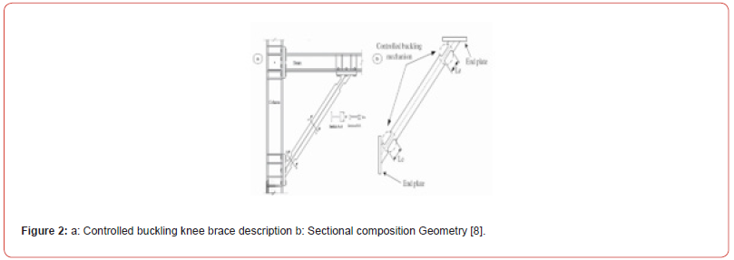
Also, the ratio of distance between the end of the knee element of the column and the length of the beam is between 0.15 and 0.3. Also, changing the cross-section of the columns has a greater effect on the lateral behavior of the frame versus the beam behavior [5]. Balendra et al. reviewed absorption energy profile in a knee bracing system through using an analytical model. An analytical model for the moment- knee member rotation relationship is obtained based on bilateral stress strain relationship that obtained from the tensile test to predict the cyclic response of the knee member [6]. Chung-Li et al. studied the seismic performance of steel frame under consideration of the buckling control mechanism in knee bracing in the KBRFS concentrated on a series of cyclic load tests based on SMRF mode [7]. Hsu et al. studied the seismic behavior of knee braced steel frame which was controlled by the buckling mechanism of the knee joint. In this system a particular shape of diagonal brace is attached to a knee member instead of joining to the beam-column, as shown in Figure 2. The diagonal element determines the lateral stiffness during a moderate earthquake [7]. Leelataviwat et al. investigated on the design and behavior of a deformable system that is called knee-braced moment frame (KBMF). The yield mechanism of the KBMF system is shown in Figure 3. The design of this system is based on the concept of capacity-design, which results in a ductile behavior [8].

Research Method
Numerical simulation is one of modern methods that contributes significantly to scientific progress and has wide application in most engineering disciplines. The simulation of science and modeling of a process or system are employed to evaluate and test strategies, or simulate methods for understanding the results of proposed ideas before their implementation. Numerical simulation has significant advantages in terms of cost, time, and provides the possibility of repeatability to perform real world experiments. The current research was conducted by numerical simulation using ABAQUS finite element software [9].
Relationships and definition of variables
It should be noted that various international standards support the design of steel structures in which the chemical composition and mechanical properties may vary. However, in general, these steel profiles are comparable. Various types of steel can be used in CFST such as carbon steel, high-strength steel, fire-resistant steel, air-cooled steel and so on. The properties of steel tubes should be in accordance with the standard of steel materials. In China, the size and dimensional tolerance for general sectors such as round, square, and rectangular pipes are according to national standards [10]. In the case of CFST structures, the outer profile of the steel pipe should not be less than 100 mm, and the wall thickness of the tube for the hot rolled and cold rolled sections should not be less than 4 and 3 mm respectively. For the concrete filled section, it is recommended to consider diameter larger than the wall thickness of the hollow section in order to improve the local buckling capacity via concrete [11].

D is the outer diameter of the circular or rectangular cross sections. t is wall thickness of tube and is the steel strength performance.

Model authentication
In order to control the accuracy of seismic behavior of a finite element model, it is necessary to compare the results of analytical and laboratory models. The present research was done as numerical simulation using ABAQUS finite element simulator software [9]. This comparison was made between the responses obtained from the ABAQUS finite element modeling and the laboratory research by Ballendra et al. [12]. A one-story model and a knee braced frame span investigated by Ballendra et al. the vertical (column) with height of 2800 mm, center-to-center span 3200 mm, bracing length of 3726 mm and cross-section of (125 mm × 8/8 × 125 × 125) were used and a section with dimensions of 17.2 × 17 × 100 × 100 H (kg / m) was used as horizontal members of the frame. The designed bracing included two C-shaped sections as back-to-back section with dimensions of (100 × 50 × 9.36) kg/m and with a gap size of 16mm that are joined via a plate with size of 100 × 100 × 12mm at 500mm intervals. The profile of the knee member is given in Table 1. The boundary members are ASTM-A572 steel considered as Tie in welding modeling. The type of element for modeling in the boundary members (bar, column, and support), hardeners and filler sheets which both of them form the knee braced frame, are solid elements in ABAQUS finite element simulator.
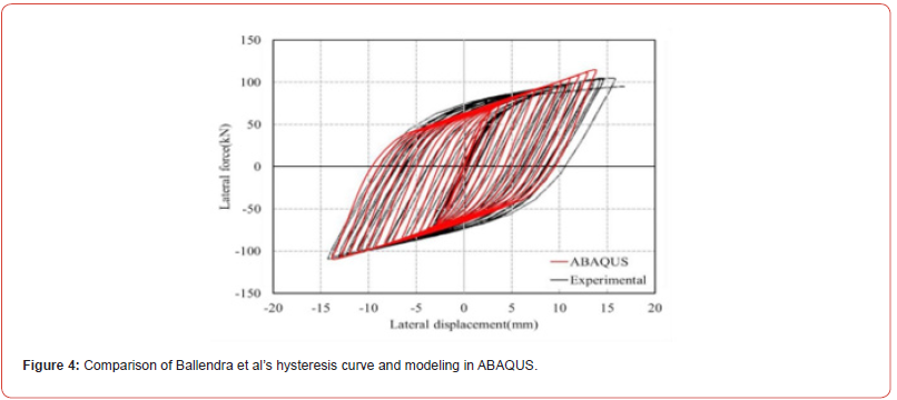
The experimental model of the knee braced frame that has been presented by Ballendra et al. is shown in Figure 4. According to Figure 4 the hysteresis diagram has been illustrated by the comparison between the experimental and modeling results in ABAQUS software. Figure 4 presents the hysteresis diagram obtained from the experimental and modeling results by ABAQUS which has a slight difference with the experimental results. The experimental and analytical results have a good match during the initial yield and elastic state when deformations are small. Differences were observed in case of large deformations. Slight difference in this curve can be due to the fact that some of the initial forces should be introduced during the construction, which is ignored in the simulation. As is shown in Figure 4, the two curves do not fully conform to each other and there are differences between them. By investigation the behavior of samples in simulation and in experimental methods, the difference can be attributed to those actions which performed in the lab (such as drilling, tightening the screw, or loosening it).
Modeling using finite element method
In a parametric analytical study, the results of experimental tests of the steel samples were used for tensile test. The values of Young’s modulus (Es), yield stress (Fy) and ultimate strain strength (Fu) are shown in Table 2. Weld Behavior in the modeled connection is assumed to be the same as the consumed steel behavior. Table 2 shows the assumed stress and strain values and Figure 5 shows the schematic diagram of nonlinear behavior. Behavior of concrete for cubic compressive strength (Fcu) over 28 days has been assumed as 28 MPa. Elastic modulus (Ec) and Poisson coefficient and tensile strength have been considered as 30 GPa, 0.2 and 2 MPa respectively. Also, in cyclic behaviors in ABAQUS software, it is necessary to define the dc (compression degradation) and dt (tensile degradation). The schematic behavior of concrete is shown in Figures 5 & 6.
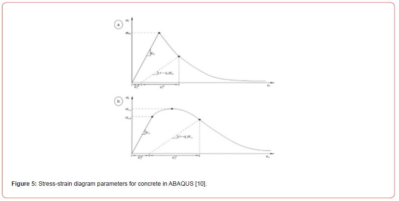
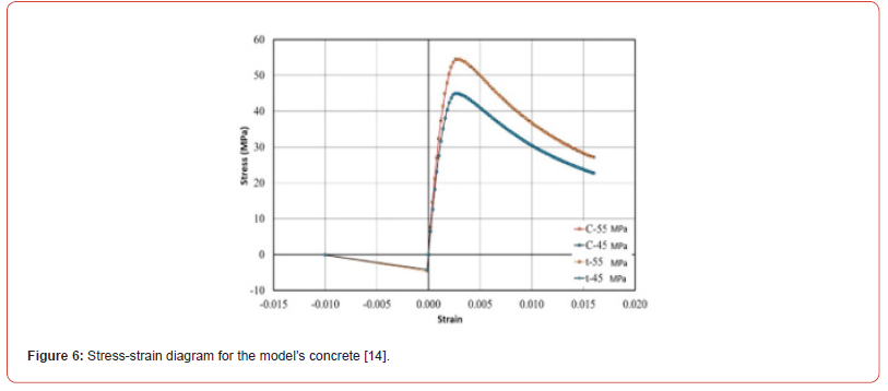
Table 1:Element Component Profile [13].

Table 2:The profile of steel materials used in the specimens.

Loading and profile of the studied connections
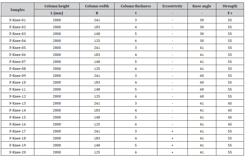
The number of analyzed models is 20 samples that a specific parameter has been considered in every specific sample. In all of the models it is considered that the steel section of the beam is fixed. The knee lengths with any slight change in angle can be adjusted, but the knee section is constant. To study the impact of the compressive strength on the mixed columns, all specimens are filled with steel concrete with a compressive strength of 45 and 55 MPa. Also, to study the impact of knee angle in the mixed columns of the specimens, the inside of the steel pipe was filled with concrete with a compressive strength of 45 MPa and three angles of 30, 41 and 60 degrees were examined. Another parameter is the eccentricity of brace from the connector axis in which the concrete in mixed columns with a compressive strength of 45 MPa was supposed. Details of the samples are given in Table 3. To test the seismicity of these samples, the AISC standard protocol was used [13]. The AISC loading history was activated by applying six consecutive cycles for 0.35%, 0.5%, and 0.75% of the relative displacement angles of the floor, and then four cycles with a maximum relative displacement angle of 1% and was continued by applying two loading cycles for each change in relative displacement angle of 1%. The place of loading is the tip of the column. The cyclic loading was applied on the samples by semi-static method in the mode of dislocation control with a low rate.
Table 3:Details of the samples.
The results of analytical studies
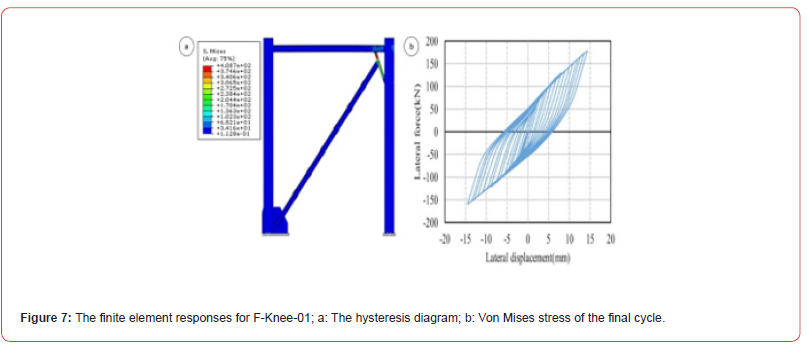
In this part the results on the cyclic behavior of the knee braced frame with the mixed column and different parameters have been discussed. Figure 7a presents the force - F-knee-01 knee braced frame displacement which was increased by the strength. In this frame the knee element has a 30-degree angle, the flange is 3mm and the width of the square column is considered as 241 mm. In Figure 7a the elastic hardness has been obtained by F-knee-01 modeling that was equal with 29.28 (kN/mm). To determine the ductility of shear yield knee, the tested frame has been reached to the inelastic strains by stimulating the frame which was based on displacement and incremental. Displacement was equal to 15 mm. Figure 7b shows the stresses in the steel frame with composite frames on the final cycle.
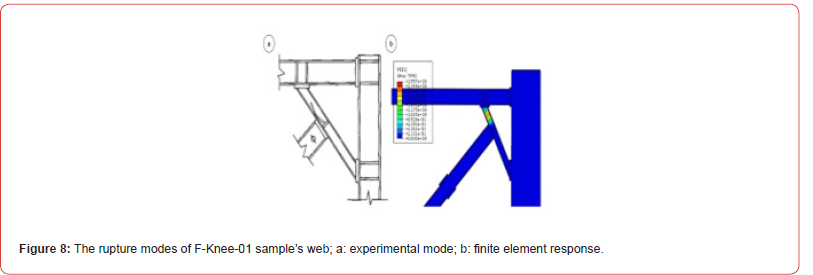
Figures 8a shows that the web failure has been happened by shearing the web. When the same base excitation (reciprocating load) is applied to increase the rate of displacement and reciprocating, the yield displacement will be equal to 1.93mm. The hysteresis curves are seen without slipping and deteriorating in strength or hardness, in spite of the frame members still have not reached their final capacity, but the knee member reaches its final limit, which operate as a fuse. Also, the wide flange beam and the mixed columns are designed to remain elastic during loading so that there is no need to repair even when the knee member is ruptured.
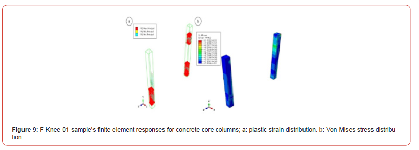
The bracing buckling reduces the energy depreciation capacity of the frame due to the slimming of the hysteresis curve. The bracing is also designed to withstand non-buckling cyclic loading. Also, the concrete in composite columns in the knee joint area severely breaks down stress transfer between the knee member and the column as shown in Figures 9a &9b. In this sample the width of the column is 241 mm, which has a high cross-sectional area than the thickness of the steel. The hysteresis diagram presents the brittle behavior with a steep slope which indicates a high hardness in the nonlinear behavior of the frame, which reduces the fame ductility. Another reason for the slimness of the hysteresis diagram shown in Figure 8a is the low thickness of the steel, which is 3 mm and the high volume of concrete compared to the steel, which has an effect on the frame behavior.
Hysteresis curves of models
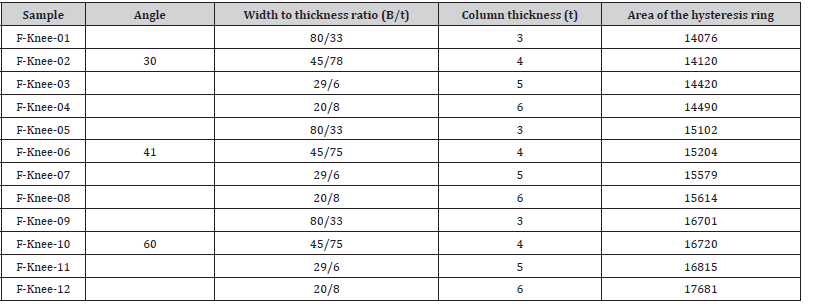
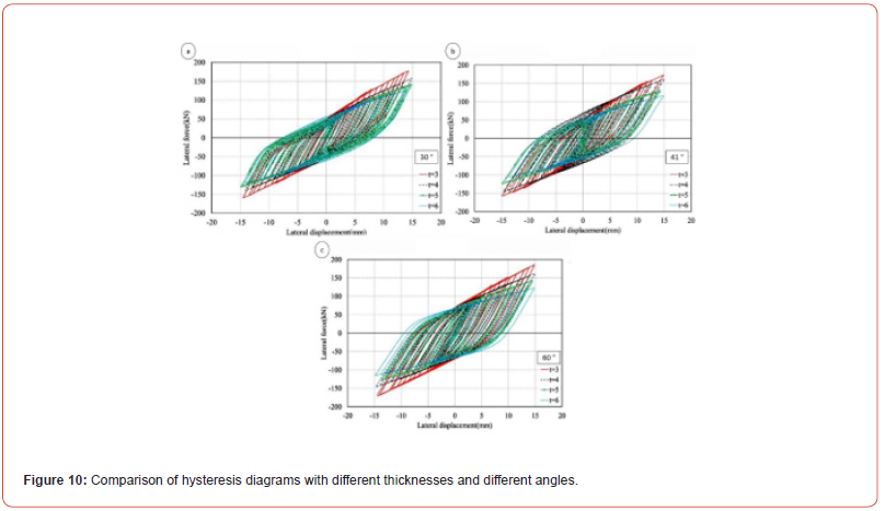
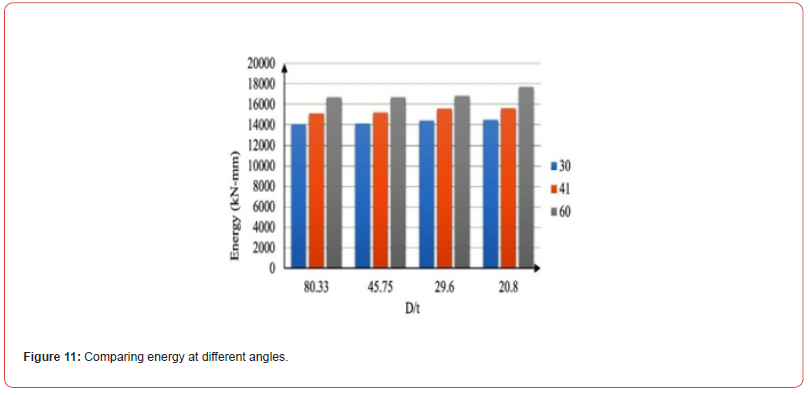
In this section, a parametric study was performed and the effect of column thickness and width on the behavior of hysteresis is investigated. In Figures 10(a-c), the effect of thickness is given for various ratios. Different angles of the knee in the mixed frame of 30, 40 and 60 degrees have significant effect on the seismic behavior of the frame. The absorbed energy values in different states for hysteresis loops are given in Table 4 and Figure11. As the Table 4 suggests, increasing the thickness leads to decrease the inner core and in result preserve the applied steel; by reducing the width of the steel tube, the separation between the concrete and the steel decreases.
Table 4:amount of energy absorbed at different angles and thicknesses.
Effect of difference of concrete strength in columns
In this section, the effect of concrete strength on concrete core of mixed columns is investigated for resistance of 45 and 55 MPa. All frame and steel features are the same for all specimens. All samples are under the constant loading protocol. As shown in the hysteresis diagrams in Figures 12(a-d) for different concrete conditions, hardness values have been increased by enhancement of the concrete strength and more energy has been absorbed by the members of the frame. Also, in Table 5, the absorbed energy values are calculated by the mixed frame (Figure 13).
.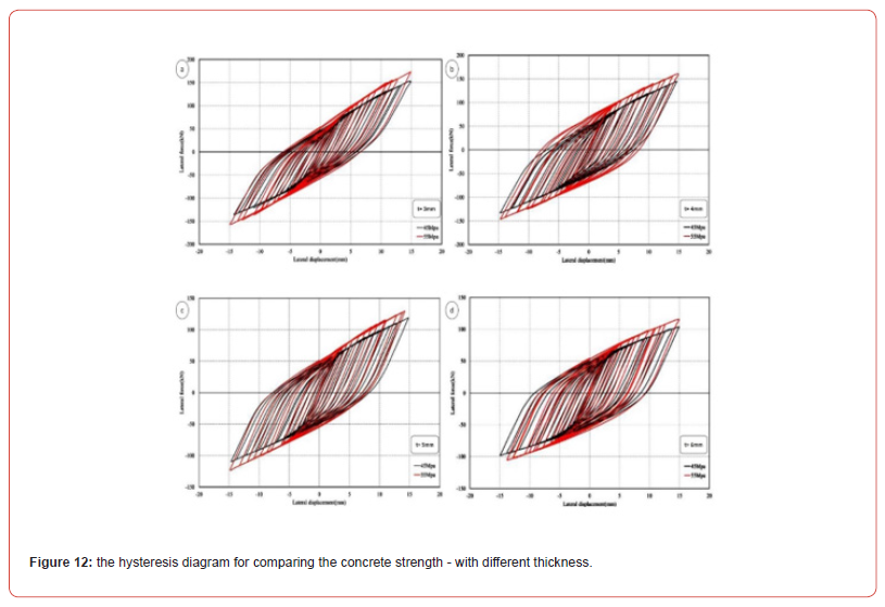
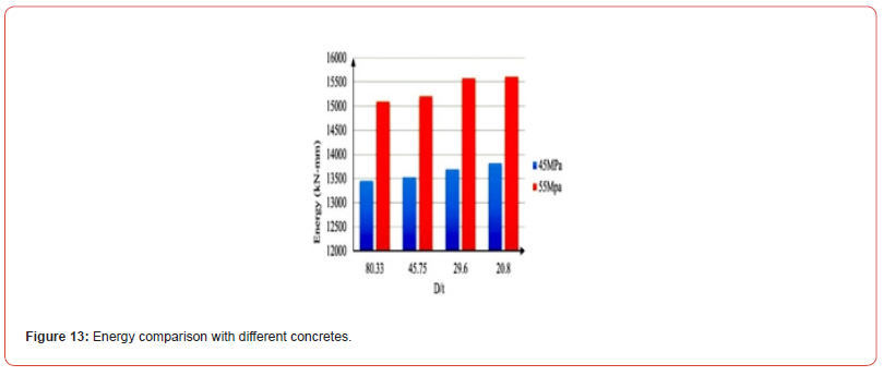
Table 5:Energy absorption values with different concrete strengths at 41-degree angle.

Investigation of hysteresis curve with eccentricity
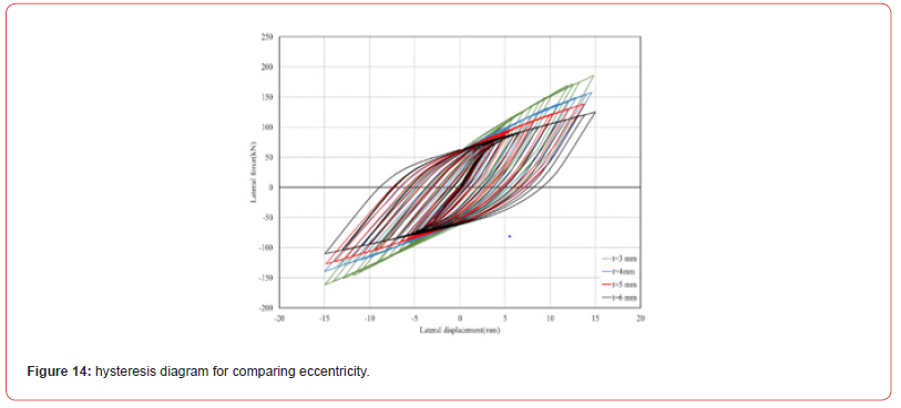
In this section the bracing eccentricity of the mixed frame of connection axis is discussed. In this comparison, the strength of the concrete is constant and equal to 55 MPa and the angle of the knee is fixed and equal to 41 degrees. Eccentricity has been evaluated in different B/t states of the column. In Figure 14, the thickness of diagrams of 3, 4, 5, and 6 mm are considered for the eccentricity. According to Figure 14, the Eccentricity symmetry decreases with increasing steel thickness, but it still has slight difference with ideal state. In the eccentricity mode, in addition to force variations, the damage of system members in the knee and the plastic joint location are changed and the system reaches to critical state. Accelerating the formation of a plastic joint that is formed earlier subject to yield the structure sooner. The result of this model is that the behavior of frame is affected by the reduction in efficiency.
Curves and comparative diagrams
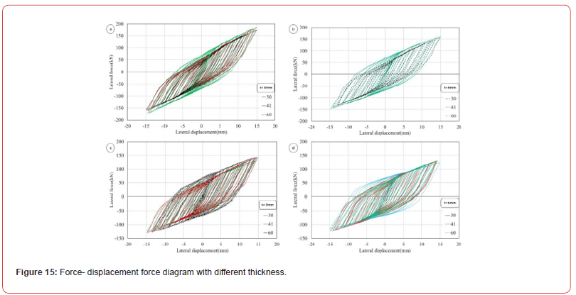
A subsequent comparison was made on the hysteresis behavior at different angles of 30, 41, and 60 degrees for thicknesses of 3, 4, 5 and 6 mm, as shown in Figures 15 (a-d). According to Figure (16-a) and obtained results, for steel column with thickness of 3 mm is at different angles, the energy absorption at 60 degree angle was greater than 30 and 41° angles but the damage to the three knee joints is higher at 30 and 60°. Because the ratio of the span is between the two values i.e. 41, in this case the transfer of force and stress is carried out with greater continuity. In Figures (15- b) and (15-c) for steel columns with thicknesses of 4 mm and 5 mm, hysteresis behavior is same for angles of 41 and 60 degrees approximately and it is less for 30 degrees, While the hysteresis curve width is reduced at angle of 30 degrees earlier than the other two angles. Also, in Figure (15-d), hysteresis behaviors at angles of 30 and 41 degrees are the same approximately, and the diagram has higher area for the angle of 60 degrees, but the plastic joint in the knee is formed earlier because of two main reasons: the first one is the geometric dimensions of the frame and the second one is uniformity of knee angle and the length to width ratio of the frame. Another obtained reason is that by changing the angle, the capacity of each stage has been changed, and the optimum angle of the knee member is achieved when the frame has the highest lateral hardness; where the 41° angle is optimum. By changing the angle of the element, the horizontal and vertical component size has been changed, which causes further damage to the column.
Comparison of hardness of samples
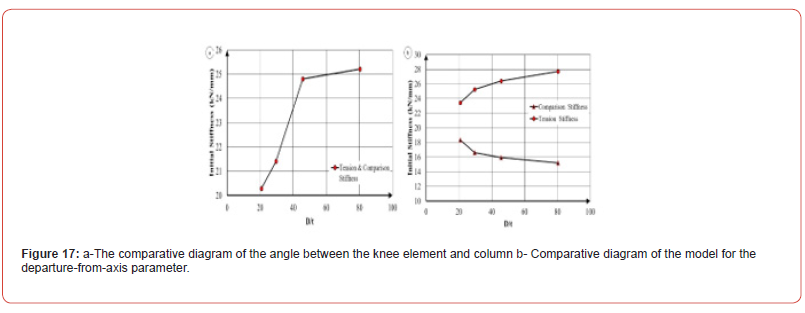
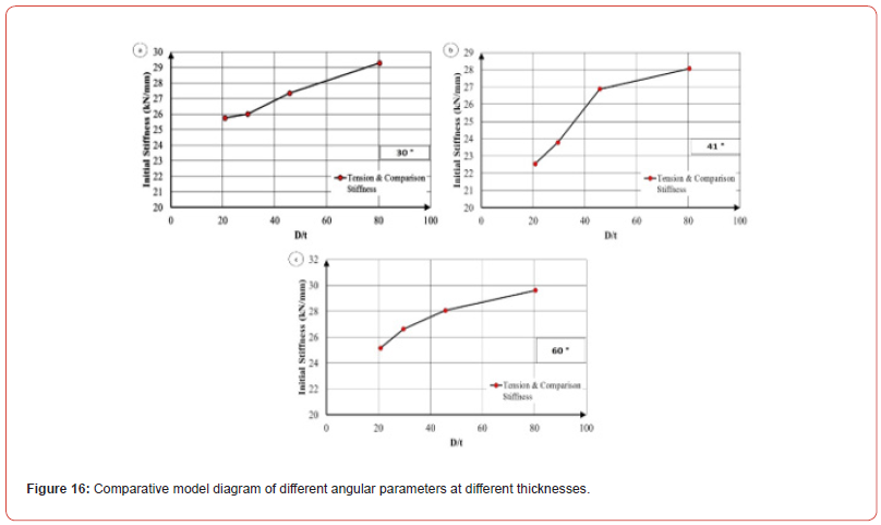
By consideration the obtained hysteresis diagrams from the parametric study, a comparison has been made between the hardness of samples by investigation on linear gradient in the elastic region. In Figures 16 (a-c) and Figures 17 (a-b) the initial hardness values of the samples are given for different states of the parameters which were studied in the previous sections; the hardness and strength values in the tensile region are increased by enhancement of column diameter to thickness ratio and the hardness show trend to enlargement in the compression section except the knee member that has eccentricity from the connection axis which demonstrate reduction tendency.
Conclusion
In this study, the effect of applying the concrete filled box column
with square section and seismic performance were simulated on
knee braced frames by finite element software. The results are as
follows:
a) By examining B/t (width to thickness ratio) of hysteresis
ring which indicates energy absorption decreases with
increasing B/t and increases with reducing the previous ratio.
This enhancement and reduction in energy was investigated by
assuming the consumed steel as constant.
b) By increasing the angle of knee member and the column
from angle 30 to 60 degrees, the amount of energy absorption
in the frame increases with respect to the hysteresis diagram.
However, the force transfer process at 30- and 60-degree angles
has been exacerbated and it was not balanced at 41-degree
angle. At 30 and 60 degrees, the distribution and concentration
of tensions were intensified and the damage to the composite
column was increased up to the same level while a better
stress transfer was observed at a 41 ° angle which is due to the
closeness of b/h of the knee to 1. Due to the appropriate height
to span ratio it showed a more favorable behavior in the stress
transfer.
c) According to the hysteresis diagrams of the knee
composite frame for different width to thickness ratios, the
hardness parameter in the hysteresis rings has reduction trend
for a sample with high thickness.
d) By reducing the strength of the concrete in the composite
frame column, the area of the hysteresis rings and the absorbed
energy decreased.
e) Eccentricity in the mixed bracing element leads to occur
difference in the behavior of structure under strain and pressure
due to removal of the knee element from the connection axis
and the slope of hysteresis rings has two different hardness
which are related to incomplete force transfer and local
damage at the attachment point of knee to the column and the
hysteresis rings are asymmetric in strain and present different
energy absorptions.
f) According to the hysteresis diagram of the mixed frame
for the same thicknesses at different angles, the energy level
for the 30, 41and 60° angles is approximately the same but the
damage at the knee to the column joint is less than 30nd 60°
angles which has a b/h of equal to 1.
References
- Clément DE (2002) Seismic analysis of knee elements for steel frames. Doctoral dissertation, University of Oxford, USA.
- Aristizabal-Ochoa JD (1986) Disposable knee bracing: improvement in seismic design of steel frames. Journal of Structural engineering 112(7): 1544-15523.
- Bourahla N (1990) Knee bracing system for earthquake resisting steel frames. Department of Civil Engineering. UK, University of Brisol, PHD Thesis, USA.
- Wongpakdee, Nattapat (2014) Performance-based design and collapse evaluation of buckling restrained knee braced truss moment frames. Engineering Structures 60: 23-31.
- Huang Zhen, LI Qing song, Chen Long Zhu (2005) Elastoplastic analysis of knee bracing frame. Journal of Zhejiang University-SCIENCE 6(8): 784-789.
- Balendra T, Sam MT, Liaw CY (1995) Earthquake -resistant steel frames with Energy dissipating knee element. Journal of Constructional Steel Research 17: 334-343.
- Hsu HL, ZC Li (2015) Seismic performance of steel frames with controlled buckling mechanisms in knee braces. Journal of Constructional Steel Research 107: 50-60.
- Leelataviwat S, Suksan B, Srechai J, Waranitchai P (2011) Seismic Design and Behavior of Ductile Knee-Braced Moment Frames. Journal of Structural Engineering 137: 579-588.
- (2011) ABAQUS/PRE V6.11.3 User manual. Hibbit, Carlson and Sorensen Inc.
- (2001) GB 50205-2001. Code for Acceptance of Construction Quality of Steel Structures. Beijing, Standard press of China.
- (2003) GB 50017-2003 Code for Design of Steel Structures. Beijing Standard Press of China.
- Balendra T, Lim ELL, Liaw CY (1994) Ductile knee braced frames with Shear yielding knee for seismic resistant structures. Engineering Structures 16(4): 263-269.
- Han Lin Hai (2001) Fire performance of concrete filled steel tubular beam-columns. Journal of Constructional Steel Research 57(6): 697-711
-
Morteza Naghipour*, Mobin Mohammadzadeh Rad and Arash Sabzi. Evaluation of the Seismic Behavior of Composite Knee Braced Frame. Cur Trends Civil & Struct Eng. 10(3): 2024. CTCSE.MS.ID.000737..
-
Composite frame; CFT column; hardness; angle of connection; energy absorption; hysteresis diagram; nonlinear analysis; Iris Publishers, Iris Indexing Sites
-

This work is licensed under a Creative Commons Attribution-NonCommercial 4.0 International License.


