


 Research Article
Evaluation of Seismic Performance Factors for Steel Multi-Tiered Special Concentrically Braced Frames
Received Date:May 05, 2023; Published Date:May 23, 2023
Abstract
Many tall industrial facilities utilize multi-tiered concentrically braced frames (MT-CBFs) as their seismic force resisting system (SFRS). In the seismic design of such buildings, it is necessary to have seismic performance factors including response modification coefficient (R), overstrength factor (Ω0), and deflection amplification factor (Cd) beforehand. These factors are not currently available in the design codes. This study intends to evaluate these factors for steel multi-tiered special concentrically braced frames (MT-SCBFs) using the methodology presented in FEMA P695. In this study, 8 archetypes were selected and designed with the initial factors of 6, 2 and 5 as R, Ω0 and Cd, respectively. Subsequently, the archetypes nonlinear models were developed, and pushover analyses were carried out first to calculate the overstrength factors. Finally, nonlinear incremental dynamic analyses were conducted to find the collapse capacities and the collapse margin ratios (CMRs). According to the results, the initial response modification factor (R=6) could meet the desirable seismic performance and can be used safely for the design of MT-SCBFs. In addition, overstrength and deflection amplification factors were obtained as 3.5 and 6, respectively.
Keywords:Multi-tiered braced frame; Seismic performance factors; Collapse margin ratio; Incremental dynamic analysis; FEMA P695
Introduction
In constructing industrial facilities and warehouses, tall single- story steel structures are generally used. Lateral resistance of these structures, at least in one direction, is provided by using concentrically braced frames (CBFs). In these tall frames, using a single bracing member is not practical nor economical, owing to considerable height of the story and high slenderness ratio of bracing members. Therefore, in these structures a system called multi-tiered concentrically braced frame (MT-CBF) can effectively be utilized. In this system, the height of the structure is divided into two or more tiers and bracing members with shorter lengths can be used in each tier. Various concentric brace configurations such as cross, chevron, and diagonal bracing systems could be used in MT-CBFs. Tiers are usually similar in terms of height and bracing configuration; however, special situations and limitations could cause the use of different heights and bracing systems in each tier. Figure 1 shows two examples of multi-tiered concentrically braced frames (Figure 1).
In seismic regions, the use of multi-tiered special concentrically braced frames (MT-SCBFs) with improved ductility and cyclic behavior is recommended. According to AISC Seismic Provisions for Structural Steel Buildings, AISC 341- 16 [1], horizontal struts are required to be installed at the level of each tier where braces intersect with the columns. The struts are needed from several engineering aspects. First, with adequate flexural strength and stiffness, they could provide torsional bracing for the columns. They could also facilitate the construction of exterior walls. Moreover, they could resist the unbalanced forces created in the braces and transfer them to the ground level through truss action. Finally, they can prevent the formation of K-type brace effect by eliminating the unbalanced forces on the columns. Braces and struts could be selected from various rolled steel sections including I-shaped, angles, channels and round or rectangular HSSs. However, the columns of MTSCBFs are often I-shaped members oriented in a way that bending about their strong axes occurs in the out-of-plane direction. This is because the columns in that direction are not braced and should have more buckling resistance. MT-SCBFs have two major differences with multi-story CBFs. One of the differences is about the distribution of seismic lateral forces among the structural components. In multi-story CBFs, the seismic lateral force is applied at each floor level owing to the existence of floor diaphragms at each level. However, in MT-SCBFs the lateral load is just applied at the roof level since there is no other floor diaphragms between the ground and the roof level. The other difference is about the unbraced length of the columns in the out-of-plane direction. The full length of the columns is considered unbraced in MT-CBFs, while they are considered laterally braced by the diaphragms at each floor level in multi-story CBFs.
The primary energy dissipating mechanism in MT-SCBFs is the nonlinear behavior of steel braces. A two-tiered concentrically braced frame under seismic loading is shown in Figure 2. In the early stages of lateral loading, compression braces in both tiers start to buckle. By increasing the lateral force, the tension brace in one of the tiers undergoes yielding which reduces the shear resistance of that tier. The difference between the shear resistances of the yielded and adjacent tiers creates an unbalanced shear force thereby inducing a large in-plane bending moment on the columns. Yielding of the tension braces begins in the weakest tier, which has the lowest shear resistance, and is known as the critical tier. Even if the tiers are completely similar, slight differences in some parameters such as material properties and geometric imperfections could cause different shear capacities in tiers thereby creating a critical tier. If the columns do not have adequate strength and stiffness, concentration of deformations in the critical tier could cause the column buckling and even collapse of the frame [2-4] (Figure 2).


Various failure limit states are recognized for the columns in MT-SCBFs. These limit states include flexural and flexural-torsional buckling in the presence of biaxial bending moments, and local buckling of column web and flanges. The design provisions of AISC 341-16 aim at preventing these limit states from happening. According to these provisions, MT-SCBFs should be analyzed under an additional loading scenario introduced in Chapter F of AISC 341-16. This loading scenario represents the progressive yielding and buckling of the braces from the weakest tier to the strongest. Despite the recognition of MT-SCBFs as a valid and practical seismic force resisting system (SFRS) in AISC 341- 16, the seismic performance factors such as, the response modification coefficient (R), overstrength factor (Ω0), and deflection amplification factor (Cd) which are necessary for designers of this system are not given. These factors are not given in chapter 12 of ASCE 7 [5] either. Several studies have been published on the seismic response of steel multi-tiered braced frames by Imanpour et al. [3,6,7]. Also, the FEMA P695 methodology has been applied by Hsiao et al. [8] to evaluate the seismic performance factors of SCBFs. However, the seismic performance factors of MT-SCBFs have not yet been investigated. FEMA P695 methodology is applicable to all existing and new SFRSs, and it has been utilized by many researchers to evaluate various structural systems. For instance, the seismic performance factors of chevron knee bracings in steel structures have been quantified by Farahi and Mofid [9]; Dual lateral systems in high rise steel buildings consisting of buckling restrained braced frames and intermediate moment frames have been evaluated by Yavarian and Ahmad [10]; and Zareian et al. [11] have applied this methodology to assess the seismic collapse performance of steel special moment resisting frames. This paper is an attempt to obtain the seismic performance factors by the advanced methodology presented in FEMA P695 [12] report. For this purpose, nonlinear static and dynamic analyses were performed on typical MT-SCBFs commonly used in practice called the archetypes. The archetypes were first designed in compliance with the American design standards (AISC 360-16, AISC 341-16 and ASCE7) [1,5,13]. Nonlinear models of archetypes were developed in Perform 3D software [14] and nonlinear static and incremental dynamic analyses were performed. The performance evaluation and conclusions are presented in the final section.
FEMA P695 Methodology Outline
The FEMA P695 report introduces a methodology for evaluating the reliability of various seismic force resisting systems which are designed using specific seismic performance factors including response modification coefficient (R), overstrength factor (Ω0), and deflection amplification factor (Cd). Definitions of these factors based on the idealized pushover curve are shown in Figure 3 and discussed in the following sections (Figure 3).

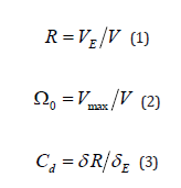
Response modification coefficient, as shown by Eq. (1), is defined as the ratio of elastic base shear, VE, to the design base shear, V. Elastic base shear is the maximum base shear that develops in the structure, if it remains elastic under severe earthquakes and none of the components experience inelastic behavior. Design base shear is the shear force used for designing the structure in an elastic range. In fact, it causes the first yielding of the structure, which makes the structure behave in a nonlinear manner and the stiffness gradually decreases afterwards. Considering the fact that the structure is designed under a reduced force instead of a real earthquake and allowed to act nonlinearly, the probability of experiencing damage under severe earthquakes increases. However, the designed sections are smaller, and the project is more cost- effective, in addition to the fact that the deformation capacity of the structure is used in the best way possible. Overstrength factor is defined as the ratio of maximum base shear of a fully yielded structure, Vmax, to the design base shear, and considered as a safety factor in the strength design procedure (see Eq. (2)). This factor is used in the design of force-controlled structural components such as the columns and their splices in MT-SCBFs. These structural elements have brittle behavior and limited ductility when subjected to forces more than their yield strength. If the overstrength factor is not utilized in the design of these members, the structure may collapse prematurely. Elastic displacement of a structure, calculated under the reduced design seismic force, is significantly smaller than the actual displacement due to the nonlinear behavior of the structure during a real earthquake. In order to calculate the actual displacement of the structure, the elastic displacement should be multiplied by the deflection amplification factor, which is defined as the ratio of the maximum roof drift of a fully yielded structure, δ, to the maximum roof drift of the elastic structure, δE/R, and could be calculated by Eq. (3).
The proposed methodology by FEMA P695 can provide a guidance to develop design criteria by applying probabilistic assessment of structures collapse risk. Evaluating the sufficiency of seismic performance factors according to this methodology is based on five main steps including required system information, archetype development, nonlinear model development, nonlinear analysis, and performance evaluation. In the first step, it is required to obtain a complete set of data about the proposed SFRS. The required information includes the system possible configurations, material properties, inelastic energy dissipation mechanisms, common range of applications, design criteria and test results. Based on the information gathered in the first step, a number of structural archetypes must be selected and designed in a way that covers all possible applications of the SFRS. The number of archetypes should be large enough to encompass the feasible design space, and also limited to avoid prohibitive computational cost. Subsequently, the archetypes should be categorized into different performance groups based on their common characteristics including their configurations, periods, and seismic and gravity loads intensities. After designing the archetypes, nonlinear models must be developed featuring the principal collapse modes of the SFRS. Since all of the collapse modes could not always be simulated, FEMA P695 suggests a further method to consider the effects of non-simulated collapse modes on the system. As the next step, using the nonlinear models, nonlinear static and dynamic analyses should be conducted. At first, nonlinear static analyses are performed in order to validate the nonlinear models and provide statistical data on system over-strength, Ω, and period-based ductility, μT. Nonlinear dynamic analyses are eventually conducted to find median collapse capacities, ŜCT, and collapse margin ratios, CMRs, for each of the archetype models. According to FEMA P695 methodology, the desirable performance of a seismic force resisting system is met if the probability of collapse due to the maximum considered earthquake (MCE) ground motions will be less than a prescribed amount which is considered 10% for each performance group and 20% for each archetype. The collapse probability of each archetype is quantified by collapse margin ratio, CMR, which is defined as the ratio of median collapse intensity, ŜCT, to the MCE ground motion intensity, SMT. The calculated CMR for each archetype should be multiplied by its spectral shape factor (SSF) in order to determine the adjusted collapse margin ratio, ACMR. Spectral shape factor values are presented in a table based on the fundamental period, T, and period-based ductility, μT.
After calculating the ACMRs for each archetype and performance group, they should be compared with the acceptable values presented in a table classified based on the total collapse uncertainty, βTOT. The total collapse uncertainty is a function of four sources of uncertainties including βRTR, βDR, βTD, and βMDL which shows record- to-record, design requirements, test data, and modelling uncertainties, respectively. Acceptable performance is achieved when the calculated ACMRs do not surpass the acceptable limits [12].
Selecting the Archetypes
In order to evaluate a SFRS based on the FEMA P695 methodology, some typical structures (named archetypes) with such system are required to be selected and designed. Variables including occupancy and use, elevation and plan configuration, building height, and seismic design category are influential on the behavior of SFRSs and thus, must be considered in selecting the archetypes. After selecting the archetypes, they should be classified into different performance groups based on their common features in configuration, period, and seismic and gravity loads intensities. Steel MT-SCBFs are generally used in industrial buildings. Therefore, industrial occupancy is assumed for the archetypes and gravity load intensities are determined accordingly. Dead and live loads of the roof are assumed to be 1.2 kN/m2 and 0.96 kN/m2, respectively, and the weight of exterior walls are taken equal to 1.2 kN/m2 [3]. All the archetypes have the same plan configuration with the dimensions of 120×54 m, and two cross-braced frames with the span of 6 m are placed in each direction. According to FEMA P695 methodology, upper and lower bound of the most severe seismic design category, Dmax and Dmin, should be considered in designing the archetypes. The height of the structure is a determining factor in estimating the fundamental period of the structure. The range of archetypes should vary from short-period to long-period configurations since their responses are different. The boundary between long-period and short-period is defined as the transition period, Ts. The value of Ts is 0.4 s and 0.6 s for the lower bound of Seismic Design Category D (SDC Dmin) and the upper bound of Seismic Design Category D (SDC Dmax), respectively [12]. As a result, different heights of 9m, 13m, 17m and 21m are selected for the archetypes. The first tiers in all archetypes are considered to be 5m and the other tiers are 4m. Performance groups are introduced in Table 1. In order to name the archetypes, the height of structure and seismic design category are used in sequence. In “9Dmax”, for example, 9 indicates the height of the frame and Dmax is the seismic design category. Figure 4 illustrates the configuration of selected archetypes, the position of columns and struts, and the brace connections (Table 1) (Figure 4).
Table:Summary of the selected performance groups.


Designing the Archetypes
The design process begins with making some assumptions. Columns and struts of A992 steel and braces of A500 (GC) steel were considered as the structural members. Building codes including ASCE 7 [5], AISC 341 [1], and AISC 360 [13] were adopted for designing the archetypes. Seismic performance factors, which are presented in Table 12.2- 1 of ASCE 7, were necessary in designing the archetypes. However, MT-SCBFs are not incorporated in that table. The coefficients for SCBFs (R=6, Ω0=2 and Cd=5) were used instead since it was judged to be the closest SFRS to MT-SCBF available. According to part 5.2.6 of FEMA P695, the basic load combination for design is (1.2+0.2SDS) D+L+QE. Gravity loads were mentioned in the previous section. The design seismic loads were obtained from ASCE 7, employing the Equivalent Lateral Loading method (EQL). Fundamental periods were calculated according to part 5.2.5 of FEMA P695 and spectral values were obtained from Table A-1A and A-1B of FEMA P695. Initially, braces were designed for the controlling compressive force caused by the seismic load, and columns were subsequently designed under simultaneous compression force and biaxial bending moments. The compression force applied to the columns consisted of two parts arising from gravity loads and seismic loads. The gravity part was calculated based on the aforementioned dead and live loads, and the seismic part was calculated considering the critical scenario in which the braces reach their expected strength in tension, compression, or post-buckling.
Yielding and buckling of the braces does not happen simultaneously in MT-SCBFs. Progressive yielding and buckling of the braces along the frame height causes shear differences between the tiers, inducing an in-plane bending moment on the columns. Dissimilar to SCBFs, this moment must be considered in designing the columns. The approach presented by Imanpour et al. [7] was employed in order to calculate the in-plane bending moments of the columns. According to this approach, the tier with the lowest shear strength was considered as the critical tier in which the compression brace was assumed to have reached its expected post-buckling strength. While other compression and tension braces have reached their expected buckling and yield strengths, respectively, the unbalanced story shear, ΔV, was calculated, and the induced bending moment was obtained from Eq. (4), in which h1 and h2 are the height of the critical and the adjacent tiers, respectively [7]. Geometric imperfection effects and out-of-plane brace buckling, as described in section F2-4e of AISC 341-16, were two factors causing an out-of-plane strong-axis bending moment on the columns and were considered in the design.

Finally, the struts were designed to resist the compression axial forces and horizontal bending moments arising from the unbalanced brace forces in the critical loading scenario and out-of-plane buckling of the braces, respectively. The final sections of the designed archetypes are summarized in Table 2 (Table 2).
Table:2Selected sections for the designed archetypes.

Nonlinear modelling of the archetypes
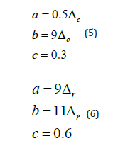
After designing the archetypes, nonlinear models were developed using Perform 3D software [14]. Nonlinear behavior of the archetypes is assumed to be concentrated in the braces, while columns and struts are linearly modelled. The provisions of ASCE 41 [15] are employed to define a nonlinear behavior for the braces. The general force- deformation relation for steel elements is shown in Figure 5. According to Table 9-8 of ASCE 41, the values of parameters a, b and c for HSS braces in compression and tension were calculated by Eq. (5) and Eq. (6), respectively, in which ΔC and ΔT are defined as the axial deformations at the expected buckling and yielding strengths, respectively.

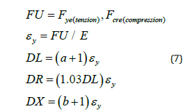
Nonlinear behavior of the steel bracing members in Perform 3D software is simulated by defining an inelastic material with a force-deformation curve of Fig. 6, in which the vertical and horizontal axes show the axial stress and strain of the member, respectively, and the parameters are calculated based on Eq. (7).

Nonlinear models should incorporate all possible collapse modes of the structure. In this regard, some of the collapse modes are explicitly simulated in the models, called Simulated Collapse Modes (SCMs), while others are considered or controlled indirectly, called Non-Simulated Collapse Modes (NSCMs). In this study, lateral collapse of the archetypes due to the nonlinear behavior of their braces is directly considered in the models by assigning nonlinear material to the bracing members. However, failure of the connections is neglected since it is assumed to be prevented owing to adequate design and details. Failure of the columns is another NSCM which should be controlled by other criteria and limit states. According to the research conducted on wide flange columns by Newell and Uang [16], columns would lose their capacity after 7% to 9% story drift. As prescribed in NIST GCR 10-917-8 [17], a story drift of 10%, was selected as a criterion to control the failure of the columns in this study.
Nonlinear analyses
Nonlinear analyses should be conducted under the gravity load combination of 1.05D+0.25L, according to part 6.1 of FEMA P695.
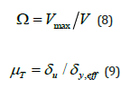
After preloading the models, pushover analyses were required to be performed in order to validate the nonlinear models and provide statistical data on the system over-strength, Ω, and period-based ductility, μT. The overstrength factor for an archetype model, Ω, is defined as the ratio of maximum base shear resistance, Vmax, to the design base shear, V, as shown in Eq. (8). The period-based ductility for an archetype model, μT, is defined as the ratio of ultimate roof displacement, δu, to the effective yield roof displacement, δy,eff, as shown in Eq. (9).
The roof displacement when the base shear is 0.8Vmax, was considered as the ultimate roof displacement. The effective yield roof displacement was calculated by Eq. (10) in which T is the fundamental period, T1 is the fundamental period obtained from eigenvalue analysis, g is the gravity constant, and W represents the seismic weight of the archetype. The coefficient C0 relates the fundamental-mode (SDOF) displacement to the roof displacement. Since the archetypes had only one floor diaphragm at the roof level, this factor was set equal to unity in this study. Figures 7(a)-(b) show the pushover curves of the archetypes, and the summary of the results is presented in Table 3.
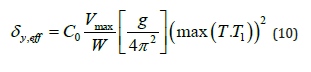
Table:3Summary of the pushover analyses.


Nonlinear dynamic analyses
Incremental Dynamic Analysis (IDA) is a method, presented by Vamvatsikos and Cornell [18], in which a structural model is subjected to one or more ground motion records while each record is scaled to increasing intensities in order to assess the seismic performance of the structure. The analyses results are presented through IDA curves in which the Damage Measure (DM) of the structure is illustrated against the Intensity Measure (IM) of the earthquake record. In this study, the maximum inter-tier drift ratio and spectral acceleration of the structure due to the applied record were taken as DM and IM, respectively. The values of median collapse intensity, ŜCT, and MCE ground motion intensity, SMT, are required for determining the collapse margin ratio, CMR, for each archetype. The calculated values of SMT, according to chapter 11 of ASCE 7, are presented in Table 4. In this methodology, incremental dynamic analyses are performed primarily for assessing the collapse intensities which are defined as the point that an IDA curve becomes relatively flat. The median values of the collapse intensities are then calculated for each archetype and considered as the median collapse intensity. According to FEMA P695, calculating the collapse intensity does not require a full IDA, but only a simplified version with at least 5 time-history analyses for each component of earthquake ground motion records. A far-field record set including 22 ground motion record pairs, provided in Table A-4A of FEMA P695, and normalized by PGVmax is used for analyzing the archetypes. Maximum inter-tier drift ratios and spectral accelerations at the fundamental period of the structures, ST, were obtained from the analyses results in Perform 3D software [14] and acceleration spectrums in SeismoSignal software [19], respectively. IDA curves and the values of SMT, ŜCT, and CMR for each archetype are presented in Figure 8(a)-(h) (Table 4) (Figure 7).
Table:4Calculated values of SMT for archetypes.


Performance Evaluation
The frequency content or spectral shape of the ground motion record set can significantly influence the collapse capacity of the structure and thus the calculated CMR values. To account for this influence, the CMR value must be modified by Spectral Shape Factor (SSF) which is a function of fundamental period, period-based ductility, and seismic design category. The SSFs are provided in Table 7-1a and Table 7-1b of FEMA P695. The Adjusted Collapse Margin Ratio, ACMR, for each archetype was calculated by multiplying the CMR value by SSF. The results are presented in Table 5.
Table:5IDA results and the calculation of ACMR values..

The effects of four sources of uncertainty including Record to Record Uncertainty (RTR), Design Requirements Uncertainty (DR), Test Data Uncertainty (TD), and Modelling Uncertainty (MDL) must be taken into account in the collapse assessment process. RTR uncertainty reflects the variability in the response of each archetype to different ground motion records. DR and TD uncertainties are related to the completeness and robustness of the design requirements and test data, respectively. Finally, MDL uncertainty deals with how well the archetype model can represent the full range of structural response characteristics and include all potential collapse modes. According to FEMA P695, RTR uncertainty for the archetypes with period-based ductility larger than 3 can be taken equal to 0.4. In this study, as shown in Table 3, the period-based ductility for each archetype is larger than 3 and hence βRTR = 0.4.
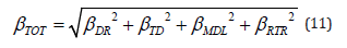
DR, TD, and MDL uncertainties were obtained from Table 3-1, Table 3-2 and Table 5-3 of FEMA P695, respectively, in which the quality ratings are linked to quantitative values of uncertainty. Considering the fact that the design criteria for MT-SCBFs have recently been included in the American seismic design provisions and have yet to be developed, the design requirements were qualified as good and βDR = 0.20. The quality of test data was considered fair since the number of experiments on MT-SCBFs was not considered sufficient and thus βTD = 0.35. The lateral collapse of braced frames is mainly due to the failure of the braces. In this study, nonlinear behavior of the braces was explicitly considered in the modelling; hence, the modelling was rated as good and βMDL = 0.20. The total system collapse uncertainty can be given by Eq. (11). The calculated value of βTOT was 0.60, which will be used in the following sections to determine the acceptable values of ACMR.
Evaluation of the response modification coefficient
In order to evaluate the collapse performance of a considered SFRS and attain a reliable R factor for the system, it is suggested in FEMA P695 that the probability of collapse due to MCE ground motions does not exceed 10% on average across a performance group and 20% for each index archetype within a performance group. Acceptable values of ACMRs are provided in Table 7-3 of FEMA P695, based on the total system collapse uncertainty and acceptable probabilities of collapse.
In the present study, the acceptable values of ACMR considering
10% and 20% probabilities of collapse were 2.16 and 1.66, respectively.
An acceptable seismic performance and a reliable R factor
are achieved when the calculated ACMRs meet the following two
criteria:
The calculated ACMR for each index archetype exceeds
the acceptable ACMR considering 10% probability of collapse
which is equal to 2.16 in the present study.
The calculated average value of ACMR across each performance
group exceeds the acceptable ACMR considering 20% probability
of collapse which is equal to 1.66 in the present study.
As presented in Table 6, all of the archetypes and performance groups have satisfied the aforementioned criteria. Therefore, it can be concluded that the initial R factor used in the design can ensure an acceptable seismic performance of MT-SCBF systems (Table 6).
Evaluation of the system overstrength factor, Ω0
According to FEMA P695 methodology, a quantitative value of the overstrength factor, Ω0, for a proposed SFRS can be calculated based on the pushover results. Average values of the archetype overstrength factors, Ω, are calculated for each performance group, among which the maximum value, rounded to half unit interval, can be reported as the system overstrength factor. As presented in Table 7, the overstrength factor for MT-SCBF system of this study can be taken equal to 3.5 (Table 7).
Table:6Performance evaluation of MT-SCBF (R factor).

Table:7Evaluation of the MT-SCBF overstrength factor, Ω0.

Evaluation of the deflection amplification factor, Cd
The deflection amplification factor, Cd, for a proposed SFRS is calculated based on the acceptable value of the response modification coefficient, R. The previously obtained R value should be reduced by the damping factor, B1, corresponding to the inherent damping of the system under investigation, β1, in order to calculate the deflection amplification factor. According to part 7-7 of FEMA P695, the inherent damping of MT- SCBFs can be assumed to be 5 percent of the critical, and the corresponding damping factor is 1. Therefore, the Cd factor can be taken equal to the R factor which is 6 in the present study.
Summary and Conclusions
In this paper, the methodology proposed by FEMA P695 was
employed to develop the global seismic performance factors for
multi-tiered special concentrically braced frames (MT-SCBFs). The
main objective of this research was to quantify the seismic performance
factors for MT-SCBFs, which are not prescribed in the seismic
design standards. To accomplish this, 8 archetypes were selected
and designed in accordance with ASCE7-16, AISC360-16, and
AISC341-16. Nonlinear models were then simulated using Perform
3D software [14], and nonlinear static and incremental dynamic
analyses were performed subsequently. Some of the main observations
and results are mentioned below:
The results of the incremental nonlinear dynamic analyses
showed that the values of adjusted collapse margin ratio for
all archetypes and performance groups surpassed the acceptable
collapse margins; therefore, the presumed response modification
factor R=6 can bring about an acceptable seismic performance for
MT- SCBFs. Moreover, the overstrength factor Ω0=3.5 and the deflection
amplification factor Cd=6 was established for this seismic
force-resisting systems.
The results of pushover analyses demonstrated that
yielding and buckling of the braces did not occur simultaneously. In
other words, progressive yielding and buckling of the braces from
weakest tier to the strongest were observed, which explains the necessity
of considering this loading scenario in the design procedure
of MT-SCBFs. Unlike multi-story SCBFs, which are designed based
on simultaneous yielding and buckling scenarios, for MT-SCBFs,
progressive yielding and buckling of the braces creates greater forces
and thus controls the design.
Acknowledgment
None.
Conflict of Interest
No conflict of interest.
References
- AISC 341-16 (2016) Seismic provisions for structural steel buildings. American Institute of Steel Construction, Chicago, Illinois, USA.
- Cano PA, Imanpour A (2018) Evaluation of seismic design methods for steel multi-tiered special concentrically braced frames. In Proceedings of the Annual Stability Conference Structural Stability Research Council, Baltimore, Maryland.
- Imanpour A, Tremblay R, Davaran A, Stoakes C, Fahnestock LA (2016b) Seismic performance assessment of multitiered steel concentrically braced frames designed in accordance with the 2010 AISC seismic provisions. Journal of Structural Engineering, 142(12): 04016135.
- Imanpour A, Stoakes C, Tremblay R, Fahnestock L, Davaran, A (2013) Seismic stability response of columns in multi-tiered braced steel frames for industrial applications. Structures Congress 2013: Bridging Your Passion with Your Profession, Pittsburgh, Pennsylvania.
- ASCE 7 (2016) Minimum design loads and associated criteria for buildings and other structures. American Society of Civil Engineers; Reston, Virginia, USA.
- Imanpour A, Auger K, Tremblay R (2016a) Seismic design and performance of multi-tiered steel braced frames including the contribution from gravity columns under in-plane seismic demand. Advances in Engineering Software 101: 106-122.
- Imanpour A, Tremblay R, Fahnestock LA, Stoakes C (2016c) Analysis and design of two-tiered steel braced frames under in-plane seismic demand. Journal of Structural Engineering 142(11): 04016115.
- Hsiao PC, Lehman DE, Roeder CW (2013) Evaluation of the response modification coefficient and collapse potential of special concentrically braced frames. Earthquake Engineering & Structural Dynamics 42(10): 1547-1564.
- Farahi M, Mofid M (2013) On the quantification of seismic performance factors of Chevron Knee Bracings, in steel structures. Engineering Structures 46: 155-164.
- Yavarian S, Ahmad R (2016) Evaluation of seismic performance factors in high rise steel buildings with dual lateral systems consisting of buckling restrained braced frames and intermediate moment frames. Procedia Engineering, 161: 680-686.
- Zareian F, Lignos DG, Krawinkler H (2010) Evaluation of seismic collapse performance of steel special moment resisting frames using FEMA P695 (ATC-63) methodology. Structures Congress 2010, Orlando, Florida, United States.
- FEMA P695 (2009) Quantification of Building Seismic Performance Factors. Federal Emergency Management Agency; Washington DC, USA.
- AISC 360-16 (2016) Specification for structural steel buildings. American Institute of Steel Construction, Chicago, Illinois, USA.
- CSI (2018) PERFORM-3D v7.0.0. Computers and Structures, Inc., Berkeley, California, United States.
- ASCE 41 (2017) Seismic Evaluation and Retrofit of Existing Buildings. American Society of Civil Engineers, Reston, Virginia, USA.
- Newell J, Uang CM (2006) Cyclic behavior of steel columns with combined high axial load and drift demand. Report No. SSRP-06/22; Structural Systems Research Project, Department of Structural Engineering, University of California, San Diego, California.
- NIST GCR 10-917-8 (2010) Evaluation of the FEMA P-695 methodology for quantification of building seismic performance factors, National Institute of Standards and Technology, Gaithersburg.
- Vamvatsikos D, Cornell CA (2002) Incremental dynamic analysis. Earthquake Engineering & Structural Dynamics, 31(3): 491-514.
- Seism soft (2018) Seism Signal Software; Earthquake Engineering Software Solutions, Pavia, Italy.
-

This work is licensed under a Creative Commons Attribution-NonCommercial 4.0 International License.


