


 Research Article
Effective Lengths of Members in Parallel Chord Trusses Made from Hollow Structural Sections
Received Date:February 28, 2023; Published Date:March 21, 2023
Abstract
Trusses with parallel chords and inclined web members tend to buckle in the lateral torsional mode when subjected to transverse loading. Load and resistance factor design specification of the American Institute of Steel Construction for hollow structural sections (HSS) specifies effective length factors for compression chords to be 0.9 for both in-plane and out-of-plane buckling. Experimental studies and the corresponding test results of twelve trusses made from square hollow structural sections are presented and briefly discussed in this paper. Design effective length factors of 0.65 for out-of-plane buckling, and 1.0 for in-plane buckling were found to be more suitable for load and resistance factor design of compression chords of parallel chord trusses made from square hollow structural sections for the laterally braced condition. For compression chords with no intermediate lateral bracing, use of an effective length factor as low as 0.3 was found to be feasible.
Keywords:Steel roof trusses; hollow structural section; effective length factors; compression chords
Abbreviations:
Table:

Introduction
Long column-free spans to create large floor spaces in buildings are always in high demand for commercial and industrial buildings. One of the common options for providing long spans is flat two-dimensional frames (also referred to as flat trusses). Frames can occupy the entire ceiling to the underside of the floor slab (or roof sheeting) and provide maximum space for services to pass through the voids created between the two parallel chords. Flat trusses are usually fabricated from hollow structural sections (HSS) and are often used to support steel roofing or concrete flooring. The use of composite construction, which consists of steel trusses and a concrete floor, is becoming increasingly popular primarily because it provides an increase in strength while concurrently improving the truss stiffness. When trusses are chosen and used as an option, several truss members namely the compression chords and some of the web members will be in compression and tend to predominantly buckle either in-plane or out-of-plane of the truss. In-plane buckling of a compression chord is possible within the unrestrained length between any two adjacent joints where the web members meet. Compression chords tend to buckle out-of-plane between the adjacent lateral bracings which are normally either the purlins or the fly-braces. Therefore, the determination of the effective length of compression chords is critical in the design of parallel chord trusses.
It is best to determine the effective length factors for both chord and web members theoretically when the joint rigidities for the corresponding loads are known. However, a relationship between joint rigidity and the combination of normal force and bending moment of the member cannot be easily established. The chord wall often experiences a small local deformation due to the compression that is applied through the web member. Local deformation of the chord wall results in an elastic restraint relative to the magnitude of the applied force. Therefore, a simple theoretical method to determine the effective length factors for chord members is often difficult to develop and complicated to use in practical designs. In the absence of a sound theoretical method, tests on flat trusses made from HSS (hollow structural sections) are one of the direct methods available for determination of effective length factors of truss members. The two known methods for the determination of the effective length factors of chords of lattice girders whose joints not supported laterally are difficult and lengthy because they are based on an iterative procedure (Dutta, 2002). The effective length factor of a chord of such trusses without intermediate lateral bracings can be considerably smaller than the laterally unbraced length of the member.
Significance of this Study
This study attempts to estimate the effective length factors for compression chords of parallel chord roof trusses made from square HSS. Theoretical basis and methods of determination of effective lengths are not reliable without the supporting test results and are often too complicated for use in routine designs. Tests were conducted in this study to determine effective length factors suitable for the compression chords of such trusses.
A Summary of Prior Studies
Several researchers have over the years attempted to systematically study truss behavior and suggested design effective length factors (K) for the compression chords depending on the type of end connection and end fixities of the concerned members. Once an effective length of the chord member is known, the method for design of a compression chord is same as that for a compression member having a known effective length. CIDECT [1,2] recommends the buckling lengths for hollow sections in lattice girders as shown in Table 1.
Table:2Effective length of hollow members in lattice girders [1].

For a truss with HSS chord and web members, the effective length factor of chords (with lateral bracing) for in-plane buckling is K = 0.9 with unbraced length of the member being the distance between any two adjacent joints. For out-of-plane buckling, K = 0.9 with the unbraced length of the member being the distance between lateral braces. For the web members, K = 0.75 for both inplane buckling and out-of-plane buckling with the unbraced length of the member being the distance between the joints. For compression chords of a lattice girder whose joints are not braced laterally, the effective length of the chord in out-of-plane buckling is considerably smaller than the actual unsupported length. Packer & Henderson [3] summarized an analytical method developed by CIDECT [4] for estimating of the effective length factors for long laterally unbraced compression chords. This method is applicable to specific types of problems, and the use of this method for routine designs can be cumbersome. When the ratio of the width of the web member to the width of the chord is small (< 0.6), the effective length factor of the web member of a lattice girder, whose compression chord is not braced laterally, may be found by using the following equation:
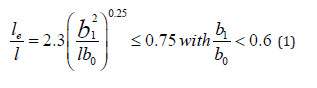
In the above expression, le is the effective length of the web member, l the distance between the intersection points of centerlines of chords and webs, b0 the external width of the square chord member and b1 the external width of the square web member. Equation (1) is valid if the upper and lower chords are parallel or almost parallel to each other, and both the upper chord and the lower chord have identical size [2]. Approximate effective length factors for double-layer grid systems (DLG) were suggested by ASCE Task Committee on Double-Layer Grids [5] as provided in Table 2.
Table:3Effective length factor K for compression chord in DLGs [5].

The corresponding theoretical effective length factors for the ideal columns are (i) 0.5 for fixed-fixed condition and (ii) 0.7 for fixed-pinned condition. A lower value of the suggested effective length factor in Table 2 for out-of-plane buckling when compared to those for in-plane buckling is essentially due to a high degree of rotational restraint provided by the web members. A smaller value of the effective length factors for the DLG members when compared to lattice girders is understandable based on the stiffness provided by the other in-plane members and out-of-plane members meeting at the member ends (i.e., at the end joints). The web members in both the open web joints and lattice girders are less stiff and do not provide the same joint rigidity as that provided in a double-layer grid (DLG) system. Madi & El-Tayem [6] suggested an effective length factor of K = 0.7 for elastic stability analyses for full section ends in DLG’s. They also recommend that the actual length of the member (not the distance between work points) be used with the effective length factor when estimating the effective length of the member. Other recommendations that are useful for determining appropriate effective length factors are given by Murtha-Smith & Bean [7] for square on offset square space frames.
A simple equation for estimating effective length factor of the compression chord having uniform cross section of a parallel chord truss for in-plane buckling was given by Bleich [8] as follows:
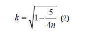
In this equation, n is the number of panels in the truss. Equation (2) gives an effective length factor of 0.77 for three panels, 0.91 for seven panels, and 0.93 for ten panels. The segment length is considered to be the distance between panel points. The restraint provided by the web members was disregarded in the derivation of Equation (2). Bleich [8] also provided tables for the effective length factors of web members of such trusses based on the following: (i) relative magnitude of the member forces, (ii) member length, and (iii) properties of the section.
American Institute of Steel Construction (AISC) Specification for Load and Resistance Factor Design (LRFD)
American Institute of Steel Construction (AISC) specifies effective length factors for compression members of trusses in Section 4 of LRFD design specifications for steel HSS [9]. The specified effective length factors are based on CIDECT recommendations [1] and are to be used for trusses unless determined by a “rational” analysis. Once the effective length factors in compression are established, the design can be performed as specified for compression members in Part 4 [9] or Chapter E of LRFD specification for structural steel buildings [10]. Unlike the recommendations of Rondal et al. [1], and Packer & Henderson [3], AISC does not differentiate between effective length factors of chords and web members of trusses with lateral support to the compression chords and those without the lateral supports.
Effective Length Factors [9]
Unless determined by a “rational” analysis, the effective length
factors (K) for compression members are to be taken as follows:
a. In trusses that are made with HSS branch (web) members
that are welded around their full perimeter to continuous HSS
chord members, the effective length factor K that is used to modify
the length between panel points for in-plane buckling or between
locations of lateral bracing for out-of-plane buckling, shall be not
less than:
K = 0.9 for chord members and K = 0.75 for branch members
b. In trusses that are made with HSS branch members that
do not meet the above requirements or with non-HSS branch members
connected to continuous HSS chord members, the effective
length factor K that is used to modify the length between panel
points in in-plane buckling shall be not less than:
K = 0.9 for chord members and K = 1.0 for branch members
The AISC specification is silent on the issue of the effective length factors to be used for compression chords in out-of-plane buckling when the compression chord is laterally unbraced.
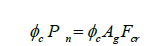
Design Compressive Strength
The design compressive strength equations of AISC specifications are as follows:
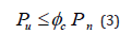
Pu is the factored compressive load acting on the chord as determined
from truss analysis, and
Pn is the nominal axial strength of the member in compression.
∅c = resistance factor for compression = 0.9
a. For inelastic range of slenderness ratio, i.e., when
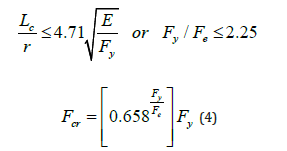
b. For elastic range of slenderness ratio, i.e., when
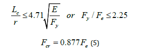
Fcr (critical stress) at the transition slenderness ratio is:

Note that Fcr is independent of Fy for the elastic range of the
slenderness ratio. Where,
Ag = gross area of member, in2
Fy = specified minimum yield stress, ksi
E = modulus of elasticity, ksi (29,000 ksi).
Lc = effective length of member, in.
r = governing radius of gyration about the axis of buckling, in.
Fe = elastic buckling stress, ksi
Test Program
A test program was developed to study the behavior of trusses made from square HSS and to determine the effective length factor for a compression chord. Contribution of purlins to the overall stability of the truss with respect to lateral torsional buckling, and the effectiveness of fly-braces in reducing the effective length of the compression chord were also studied. Complete details of the test program and the test results are presented by Pham [11], Woon [12] and Patnaik et al. [13,14].
Test Set-up
The tests were conducted with the help of a self-equilibrating rigid steel frame as shown in Figure 1.

The test trusses were designed to fit within the inside of this steel test frame. Specific details of the supports for the test trusses are shown in Figure 2.
The supports were at points slightly away from the nodes in order to suit the span that could be efficiently achieved in the rigid frame.
Measurement of Deflections
A simple method of using straight edge and a reference datum was adopted to record the deflections of the truss during testing. An arrangement for measurement of deflection is as shown in Figure 3.


Details of Test Trusses

Details of a typical test truss are shown in Figure 4.
The trusses had a span (distance between the two end supports) of 4.63 meters. The truss geometry was such that it had parallel chords and branching web members. They were made in a fabrication workshop of a local design and construct firm enabling the production of the trusses to be done as per common practice in the construction industry. The load was applied at the midspan using a loading bracket as shown in Figure 5.
Purlins were attached to the trusses as shown in Figure 6.
A typical arrangement of fly-braces is as shown in Figure 7.


The entire purlin-truss system was turned upside down since the intention was to subject the top chord to compression when the truss is loaded so as to observe and record the behavior of the top chord during the tests. Therefore, the purlins were attached to the lower chord of the truss.
The chords of the test trusses were made from an Australian
section C450LO 40x40x2.5 square HSS. This section is cold formed
to comply with Australian Standard AS1163 with residual stresses
classification of CF of the Australian design standard for steel structures
[15] and the following properties:
Ag = Gross area of cross-section = 359 mm2
E = Modulus of elasticity = 200 GPa
Fu = Specified minimum tensile strength of the
HSS = 500 MPa
Fy = Specified minimum yield strength of the
HSS = 450 MPa
Ix = Iy = Moment of inertia of the HSS section = 0.0822 x
106 mm4
Jt = Torsional constant of cross-section = 0.136 x
106 mm4
rx = ry = Radius of gyration about the x- or
y- axis = 15.1 mm
The size of the web members used in the trusses was C450LO 25 x 25 x 2.5 square HSS with the same grade of steel as the chord members. The section properties were: rx = ry = 8.99 mm, Ag = 209 mm2, Ix = Iy = 0.0169 x 106 mm4, and Jt = 0.0297 x 106 mm4.
Test Procedure
Ten trusses were tested with Z100 purlin system, and two other trusses were tested with Z150 purlin system. Z100 purlins are Z-shaped with an overall depth of 100mm and the Z150 purlins are Z-shaped with an overall depth of 150mm. For each test, the truss and the loading jack were set up, and dead loads recorded. The load was applied in increments of 5 kN, and both the vertical deflections and lateral deflections were recorded. Finally, the failure load and the failure mode were recorded when the compression chord buckled. Test truss T1-1 was tested in three stages. Stage I of testing involved testing the truss without attaching any purlins or fly-braces. Stage II involved testing of the truss with purlins in place but without any fly-braces attached. Stage III involved testing of the truss with both purlins and fly-braces attached. The load corresponding to sudden flipping and buckling of the test truss in stage I and stage II was considered to be the corresponding failure load. The load was released after the flipping occurred in each stage and the next stage testing was carried out after attaching the relevant purlins and/or fly-braces. The truss T2-5 was tested with purlins attached but without fly-braces (as in stage II of T1-1). Truss T2-6 was tested without any purlins or fly-braces attached (as in stage I of T1-1). For these three trusses, the ends of the trusses were laterally braced with the help of fly-braces as for all other trusses tested.
Test Behavior
For all the trusses, the load carrying capacity of the truss dropped suddenly with an increase in deflections when the compression chord caused buckling to occur. Tensile chord suffered little damage besides the occurrence of minor bending as a direct consequence of the point load that was applied directly to the chord at the midspan. The purlins and fly-braces did not suffer any damage and were reused in the subsequent tests. Buckling of the compression chord out-of-plane of the truss was the dominant mode of failure for five trusses (i.e., T1-1, T1-3, T1-5, T1-6 and T2-4). The other trusses (i.e., T1-2, T1-4, T2-1, T2-2 and T2-3) failed by buckling of the compression chord in the plane of the truss. Typical inplane and out-of-plane buckling of compression chords are shown in Figure 8(a) and Figure 8(b).


The failure load and the mode of failure for each test truss is summarized in Table 3.
Truss T2-5 and truss T2-6 failed by out-of-plane buckling. Truss T1-1 also failed by out-of-plane buckling in both stage I and stage II conditions.
Table:4Summary of failure loads and effective length factors at failure.

Note: Test loads and chord forces include the effect of the truss self-weight.
Coupon Tests for Material Properties
All the Series 2 trusses tested had their materials tested for tensile properties for the purpose of more accurate analysis of results. The tensile testing was conducted according to the Australian Standards on methods for tensile testing of metals (AS 1391). The specifications and the test method for tensile testing of tubular steel members are described in AS 1391 and are identical to those specified in the American Standard for Testing of Materials (ASTM, A 370 – 95). The Australian standard AS 1391 specifies the dimensions of standard test coupon and the method of tensile testing of a tubular section, such as grade C450LO 40 x 40 x 2.5 square HSS.
Test Coupons
After the trusses were tested, the coupons were cut out from the test trusses to ensure that the properties used in the subsequent analysis belong uniquely to each particular truss. The test coupons were cut out from the non-welded side of the C450LO 40 x 40 x 2.5 square HSS to make sure that the tensile properties were not distorted due to welding. The test coupons were precision machined from the members cut out from the trusses in accordance with the dimensions specified and shown in Figure 9.

One coupon was tested for each of the six trusses of series 2 trusses. The results of the tensile tests of the coupons are tabulated in Table 4.
The results of the coupon tests were higher than the specified minimum yield strength of C450LO 40 x 40 x 2.5 square HSS, having an average yield strength being 467.4 MPa. No coupon tests were conducted for series 1 trusses. Therefore, the average yield strength of 467.4 MPa was used in the analysis for effective length of compression chords of these trusses.
Table:5Results of coupon tests..

Test Results
Effective length factors of compression chords of the test trusses were determined for both in-plane buckling and out-of-plane buckling at the corresponding failure load. These factors were determined by trial and error using Equation (3) with the help of EXCEL spreadsheet for a known failure load (Pu) and with ∅c =1.0. The resulting effective length factors of the test trusses are summarized in Table 3.
The in-plane effective length factors of trusses T1-2, T1-4, T2- 1, T2-2 and T2-3 are representative values for in-plane buckling because these five trusses failed in an in-plane buckling mode of the compression chord. Trusses T1-4 and T2-1 failed prematurely without any indication of smaller load carrying capacity. All the trusses were tested out-door and the moisture from rainwater may have entered the loadcell thereby resulting in possible inaccuracies in load readings. The failure loads for these two tests may not be reliable. The remaining three trusses corresponding to in-plane buckling resulted in an average effective length factor of 0.97. Five trusses (T1-1, T1-3, T1-5, T1-6 and T2-4) failed in out-of-plane buckling of the compression chord. The average effective length factor for out-of-plane buckling for these five trusses was 0.64. It seems to be a coincidence that the fly-braces (lateral braces to the compression chord) for the test trusses are so spaced that the inplane and out-of-plane buckling of the compression chords for the test trusses may have occurred at nearly the same load. Therefore, it may not be grossly incorrect to determine the average effective length factors from all the tests for possible use in practical designs. The average effective length factor for in-plane buckling for all the ten trusses worked out to be 1.08 and the corresponding average effective length factor for out-of-plane buckling is 0.64 compared to 0.97 and 0.64 respectively based on the specific failure modes. No additional test data could be developed for effective length factors of web members because none of the trusses failed by buckling of its web members.
The failure load of truss T1-1 corresponding to the stage without purlins and fly-braces was 25 kN. The failure load corresponding to the stage with purlins but without fly-braces was 30 kN. The effective length factors determined for trusses T1-1 (stages I and stage II), T2-5 and T2-6 are summarized in Table 3. The average effective length factor for the compression chord without any intermediate lateral bracing was 0.24. The effective length reduced slightly to 0.21 when the purlins are attached. These values are in the same range as the values presented in the examples by Rondal et al. [1], and Packer & Henderson [3]. AISC does not recognize the substantial decrease in effective length factors for compression chords without intermediate lateral bracings, and this can have a major effect on the outcome in practical designs. The theoretical method of CIDECT [4] that is summarized by Packer & Henderson [3] is not directly applicable to the test trusses of this study because each test truss was tested by itself (not in pairs) and had no floor beams attached at the tension chord level. However, the effective length factors for the compression chord of the test trusses were attempted to be determined after taking into consideration suitable assumptions.
Two cases relate to the trusses tested without lateral braces in
this study:
I. when no purlins or fly-braces are attached
II. when purlins are attached but no intermediate fly-braces are
attached
With an assumption that the moment of inertia of the floor beams is zero for case (i) (i.e., no contribution to joint stiffness from bending of the floor beam), the effective length factor was determined by Mouty’s method to be 0.95. The distance between trusses does not enter the calculations if the moment of inertia of the floor beams is zero. For case (ii), the purlins may be assumed to behave somewhat like the floor beams. A nominal moment of inertia of the purlins of about 0.324 x 106 mm4 results in a reference effective length of about 0.3. For this case, a spacing of the trusses of up to 6 meters leads to a reference effective length factor of 0.3 or under. If the spacing is increased to say 15 meters, the reference effective length factor increases marginally to 0.32 indicating that the distance between adjacent trusses does not significantly affect the results.
In general, the effective length factors for out-of-plane buckling are smaller than the corresponding effective length factors for inplane buckling. This agrees with the recommendations of previous studies [5]. Lateral bracings in the form of fly-braces can be considered to provide adequate lateral support such that the positions of the segment ends remain relatively unchanged after the application of compressive force in the chord for out-of-plane buckling. However, the location where web members provide the required support to prevent in-plane buckling does not remain unchanged after the application of compressive load in the chords because the truss nodes deflect within the bending plane. The diagonal web members as arranged in the test trusses seem to be less effective in providing the required rotational restraint against in-plane buckling of the compression chord than the corresponding effectiveness of lateral supports that are provided by fly-brace-purlin combination. Furthermore, the web members are expected to provide some stiffness and restraint against lateral torsional buckling of the truss, and consequently contribute to smaller effective length factors in the out-of-plane buckling mode. The same web members are unable to completely prevent rotation of the joints to reduce the tendency of the compression chord to buckle in-plane. This, along with the relative vertical deflection between the adjacent ends of a compression chord segment may be causing the effective length factors for in-plane buckling that were developed from the tests to be nearly equal or slightly greater than 1.0. Such behavior can be explained as being like the effective length factors of columns in unbraced building frames with rigid joints where the effective length factors are greater than 1.0 because of the lateral drift (sway) of the frame (Figure 9).
Discussion and Design Recommendations
Interpretation of test results to determine the effective length factors depend on the related specifications. Some of the findings of Pham [11] are reported by Patnaik et al. [13,14] along with some simplified guidelines for the design of parallel chord trusses made from square HSS. The simplified guidelines suggested include those for a rapid analysis for determining the member forces and the corresponding truss deflections. These guidelines were based on Australian design standard for steel structures [15]. The effective length factors were slightly greater than those recommended in this paper because the recommendations in this paper are intended to be used in conjunction with AISC specifications [9]. This minor difference arises because the different equations used for the design of compression members in different design standards are based on their respective load factors, load combinations and the specified values of resistance factors. It is recommended that the effective length factors suggested in this paper be used with the design equations of AISC LRFD specifications [9,10] as given in Equation 3.
It is recognized that the scope of the reported test program is limited and focused on the specific needs of the sponsor of the project. Furthermore, it seems to be a coincidence that the fly-braces for the test trusses were so spaced that the in-plane buckling and out-of-plane buckling of the compression chords occurred at nearly the same load. More tests are required using revised design of test trusses to isolate the two modes of failure from each other. More tests are also needed with different variables, such as (i) spans, (ii) span to depth ratios, (iii) different member sizes, etc. to generalize the findings reported in this paper. However, it seems possible to significantly reduce the effective length factor of 0.9 suggested for out-of-plane buckling by AISC [9] to a much smaller value of around 0.65. Use of a larger effective length factor is conservative and is more acceptable than the use of a smaller effective length factor which will result in larger member capacities than what is determined when a larger effective length factor is used in a design. The issue of the effective length factor of 0.9 as suggested by the specification for in-plane buckling of the compression chord needs to be revisited because this study indicates that an effective length factor of 1.0 is more appropriate for such cases. No recommendations can be made for effective length factors for web members as none of the trusses failed by buckling of its web members. More tests are required with test trusses designed to fail in the desired mode to further study the effective length factors for web members. The average effective length factor of laterally unbraced compression chord was found from the tests to be 0.24, which is of the same order as the effective length factors obtained in the examples given by Rondal et al. [1] and Packer & Henderson [3]. The theoretical predictions based on the mentioned assumptions support the effective length factor for such cases to be in the vicinity of 0.3. The theoretical method predicts a reference effective length factor of 0.95 for the case of test trusses without purlins and fly- braces attached. This indicates the significant effect the purlins have on the effective length factor of the compression chord of trusses when the compression chord is laterally unbraced. However, this large difference in the effective length was not observed in the tests of the current study suggesting that Mouty [4] method may not be applicable to such trusses.
The test results seem to support the general notion that the joints are hinged with K = 1.0 for most truss members during inplane buckling. In reality, the truss members are partially fixed at the joints. As a consequence of this, the effective lengths are expected to be smaller than 1.0. When no precise calculations are available, common practice is to take K = 1.0 for both in-plane buckling and out-of-plane buckling of the members. This is acceptable for inplane buckling but will be conservative for out-of-plane buckling. A more comprehensive study is required to confirm these preliminary findings on the effective length factors of compression chords for in-plane buckling and out-of-plane buckling with intermediate lateral bracings and without lateral bracings. A greater decrease from a value of K = 0.9 is possible for the effective length of compression chords for out-of-plane buckling for trusses without lateral bracings. However, a systematic and comprehensive research study is required to establish these effective length factors and to generalize these findings.
Conclusion
Based on the test results and findings of this study, the following
are the key findings:
1. An effective length factor of 0.65 for out-of-plane buckling
and an effective length factor of 1.0 for in-plane buckling are appropriate
in the design based on load and resistance factor design
(LRFD) of the compression chord of a parallel chord truss made
from square hollow structural sections (HSS) when the compression
chord of the truss is laterally braced.
2. When the compression chord of such a truss is not laterally
braced, the effective length factor for out-of- plane buckling
can be significantly smaller than 0.9. The tests and an approximate
method used in this study indicate that the effective length factor
for such cases can be as small as 0.3. Recognition of this aspect
leads to an economical outcome when designing parallel chord
trusses made from square HSS.
3. Additional studies are needed to expand the database of
test results for parallel chord trusses made from HSS and to develop
sound theoretical methods to predict the effective length factors of
the compression members of such trusses.
Acknowledgment
The authors acknowledge the support of Brown and Joy (Commercial & Industrial Design and Construction), Canning Vale WA, Australia in carrying out this study. In particular, the support of their design manager Mr. Clive McIntyre was valuable in the completion of the study. K. Pham and Y.T. Woon performed the tests reported in this study as part of their final year projects.
Conflict of Interest
No conflict of interest.
References
- Rondal J, Würker KG, Dutta D, Yeomans N (1992) Structural stability of hollow sections. CIDECT Report, Germany, 1992.
- Dutta D (2002) Structures with hollow sections, Ernst & Sohn – a Wiley company.
- Packer JA, Henderson JE (1997) Hollow structural sections connections and trusses, Canadian Institute of Steel Construction, Ontario, Canada.
- Mouty J (Editor) (1981) Effective lengths of lattice girder members, CIDECT Monograph No. 4, Boulogne, France.
- Cuoco A (Ed.) (1997) Guidelines for the design of double-layer grids, ASCE Task Committee on Double- layer grids, ASCE, New York.
- Madi UR, El-Tayem AA (1991) On the Effective Length of Compression Members in Double- Layer Grids. International. Journal of Space Structures, Multi-Science Publishing Co., UK 6(1).
- Murtha-Smith E, Bean JE (1989) Double Layer Grid Space Frame Buckling. International Journal of Space Structures, Multi-Science Publishing Co., UK, 4(3).
- Bleich H (1952) Buckling of metal structures, McGraw-Hill Book Company Inc.
- American Institute of Steel Construction – AISC (2001) Load and resistance factor design specification for steel hollow structural sections, AISC, Chicago IL.
- American Institute of Steel Construction - AISC (2017) Load and resistance factor design specification for structural steel buildings, (also available in Steel Construction Manual 15th Edition), AISC, Chicago IL.
- Pham KD (1999) A study of flexural-torsional buckling of portal trusses with hollow sections, Final year research Project, Curtin University of Technology, Perth, Australia.
- Woon YT (2000) A study of flexural-torsional buckling of portal trusses with hollow sections, Final year research Project, Curtin University of Technology, Perth, Australia.
- Patnaik AK, Pham KD, McIntyre CN (2000) Design of Parallel Chord Steel Roof Trusses made from Square Hollow Sections. Australian Journal of Structural Engineering., IE Australia 3(1-2): 99- 108.
- Patnaik AK, Pham KD, McIntyre CN (2002) Authors Closure of ‘Design of Parallel Chord Steel Roof Trusses made from Square Hollow Sections.’ Australian Journal of Structural Engineering, IE Australia 3(3): 229-230.
- Australian Standard AS4100 (1999) Steel structures, Standards Australia, Sydney.
-

This work is licensed under a Creative Commons Attribution-NonCommercial 4.0 International License.


