 Research Article
Effect of Concrete Strength on the Design of Prestressed Concrete Bridge Girders
Mehwish Mustafa* and Afzal Javed
University of Engineering & Technology, Lahore, Pakistan
Mehwish Mustafa, University of Engineering & Technology, Lahore, Pakistan
Received Date:January 07, 2025; Published Date:January 17, 2025
Abstract
In this research a study on design of high strength prestressed concrete bridge girders have been performed. The grillage analysis of standard National Highway Authority (NHA) Pakistan two-lane bridges with all the eight types (type A – type H) of standard NHA cross sections of I-girders is carried out using STAAD Pro.2007. The significance of the research is to have better understanding of using high strength concrete and evaluating its incremental effect on the span of girders. Observations made. From this research shows that by increasing specified concrete compressive strengths (fc’) from 41 MPa (6000 psi) to 69 MPa (10000 psi) having girder spacing of 2.5m center to center and the average increase in span length is 25 %.From these results it is obvious that that by increasing concrete strength of girders the span length increases for all the eight types of girders. The maximum increase in span range is for girder “Type G” i.e. 31%. According to NHA the span range specified is from 29m to 37m, concrete strength used is 5000 Psi and the depth of the section is 2400mm.But if we use high strength concrete from 6000 Psi to 10000 Psi the same girder depth of NHA can be used for span length up to 48.5m.
Introduction
Rapid increase in population in urban areas put lot of pressure on traffic network and therefore the use of flyovers, underpasses, express ways etc. is frequently adopted to solve the traffic problems. Economic conditions of the country and the available funds are often dictating the selection of the solution i.e. flyovers, under passes etc. The selected solution must not compromise the safety factor. Historically, bridges have being used in the transportation system. Achieving long span with adequate structural strength of the bridge is a challenging task for the bridge designer. Different types of bridges e.g. hanging bridge, steel frame bridge, box Girder Bridge, etc. is utilized depending on different types of material and design practices. The efficiency of the pre-stressed girder depends upon the strength of the concrete, which in turn depends on the mix design of the concrete. The required ultimate strength of concrete (28 days strength) is obtained by using good quality cement, sand and aggregate plus adding suitable admixtures/ plasticizers and reducing the water / cement ratio. Recent codes of practice specify an ultimate concrete strength of 6000psi (42MPa) as a transition point for pre-stressing. High-strength concrete enhances the performance and also because of its improved impermeability, durability and accelerated strength gain it is helpful in assisting the deterioration of the bridge structures problems. For about 30 years HSC is rapidly being used in bridge construction. The definition and maximum strength criterion for high strength concrete varies from country to country. However, usually HSC is any concrete that has compressive strengths that exceed that of concrete in normal use, has a low water/cement ratio and may have additions and admixtures. The limits of achievable strength and durability properties for concrete are being stretched further with considerable research going on to make the use of HSC easier and more common place. Different shapes of the pre-stressed bridge-girders have been used in practice among which, I-, W-, T-, inverted T, double T and hollow box-sections are the most common.
Table 1:

Table 2:

Table 3:

In Pakistan, usually I- girders are used. e.g., in Flood Damage Restoration Project Swat, I-girders with a specified strength of 5000 Psi (34Mpa) have been used in the bridge construction. HSC with ultimate strength of 8000Psi (52Mpa) is attainable now by using specific types of aggregates and super-plasticizers. Different strengths of concrete with ultimate strength of 10,000Psi (64MPa) for pre-stressed bridge girders are analyzed in this study. The focus of the study was to obtain the maximum span length with by using high strength concrete. Design software STAAD PRO. 2007 was utilized in analyzing the NHA I-girder cross-sections for the applied load. Catherine French, All els. (October 1994) assessed the viability and performance of HSC for bridge girders. Results showed that for Type I girders with several girder spacings, an increase in concrete compressive strengths from 41 MPa (6000 psi) to 83 MPa (12000 psi) results in approximately 25% increase in the maximum span lengths.
Timothy and Kenneth (1980) reported that an increase in compressive strengths from 41 MPa to 69 MPa results in more than 20% increase in spaning capacity for Type I girders and the girder spacing can be more than doubled for a given span length. This finding is in line with the results obtained by Catherine French, All els. Russell (1994) reported that an increase in compressive strengths from 41 MPa to 69 MPa results in a 25% increase in spaning capacity for AASHTO Type IV girders when 0.5 in. diameter strands are used.
Significance
Normal Strength Concrete (NSC) is having the problems of
large self-weight of concrete, High matrix porosity, Micro and macro
cracking, Corrosion of embedded reinforcement and Sulphate
attack, and lacks the required workability in some large concrete
structures, such as high-rise buildings, bridges, and structures under
severe exposure conditions. By increasing concrete strength
and performance, the required thickness of concrete members and
the cost of concrete structures can both be reduced. High Strength
Concrete (HSC) and generally Higher Performing Concrete Materials,
or High-Performance Concrete (HPC). The development of new
technology in the materials sciences is progressing rapidly. Advanced
composite construction materials and HSC / HPC are gaining
wide acceptance in the construction industry of today, and are
well positioned for increasing proliferation in use in the future. HSC
and HPC will continue to make important contributions to the enhanced
quality and efficiency in the construction of infrastructure
and our communities in the present century.
a. longer spans can be achieved.
b. HSC makes it possible to increase the load-carrying capacity
without increasing member sizes in the bridge substructure
and superstructure.
c. HSC helps increase the durability of bridge members. This is
specifically true for ‘high performance concrete’, where concrete
mixes can be produced to meet specific durability requirements
such as low permeability for bridges exposed to a
marine environment.
d. Lower maintenance costs and longer service lives are achieved.
e. The speed of construction can be increased with the use of
high early strength Concrete and more workable concrete
(however, there may be an increased risk of Early age thermal
cracking).
Objectives
The main objectives of the research are given below:
a) Carry out structural analysis of eight types of I-girders of two
lane standard National Highway Authority Bridge using high
strength concrete. Concrete strength considered in this analysis
varies from 42MPa (6000psi) to 69MPa (10000psi).
b) Evaluate the effects of using high strength concrete on increasing
the span of bridge girder without compromising on stability
and strength of the bridge. Prepare graphs and tables using
high strength concrete for comparison and conclusion.
c) Make recommendations to adopt a new design regarding safety,
aesthetics and economy for the bridge designers.
Girder Section
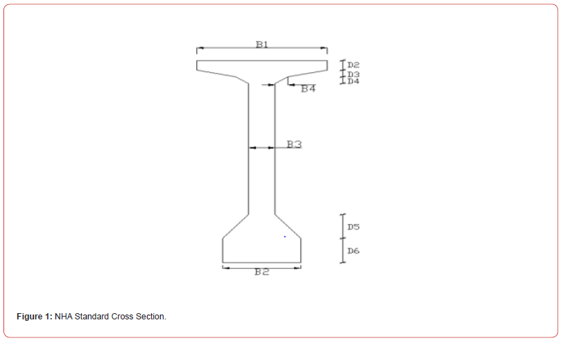
The girder section selected for the study is of typical NHA I-girder cross section. NHA has introduced 8 types of cross sections to the bridge designers i.e. from type A to type H. All these sections have different dimensional parameters from each other. In “NHA Standard Cross sections of Girders” the concrete strength defined for all these girders is 5000 Psi. And the span range for all these cross sections for strength 5000 Psi is shown in the following table.
Stresses for Flexural Design at Different Stages
For a simply supported beam different equations for the computation of stresses at extreme top and bottom fibers are provided for the precast concrete sections. Stresses at initial stage, intermediate stage and at final stages are calculated to compute flexural stresses according to conventional flexural design of beams. Theses stresses are than compared with allowable stresses according to AASHTO Standards of Specifications. The sign conventions used in these stresses equations represents negative for compression and positive for the tension at extreme fibers.
Initial Stage
At this stage, the initial prestressing force (immediately after transfer) is applied to the precast girder section before casting of the concrete slab. Initial losses in prestress force are take place during and immediately after transfer of prestress.

Intermediate Stage
At this stage, the effective prestressing force (after losses) and the total dead load are applied on a composite section, when the cast-in-place concrete slab hardens. The immediate losses and all the time-dependent prestress losses are contributing at this stage.

Service Stage
At this stage, the effective prestressing force (after all losses) plus the total dead load, total live and impact loads are to be applied on a composite section, after the cast-in-place concrete slab hardens. Total losses are included the immediate losses and all time-dependent losses.

Where:
Ft, Fb = concrete stresses at top and bottom extreme
fibers, respectively
Pi = initial prestressing force
Mo = moment due to self-weight of girder section
Pe = Effective prestressing forces
Mdp = Moment due to dead load of slab and diaphragms
e = eccentricity of tendons from center of gravity of the concrete
section
AC = cross-sectional area of the precast girder
Zt , Zb = section moduli of the precast section alone at the extreme
top and bottom fibers, respectively
Ml = Moment due to live load plus impact
Mdc = Moment due to super imposed dead load (footpath, barrier,
wearing surface)
Allowable Stresses at Transfer
Allowable tensile and compressive stresses from the AASHTO Standard Specifications are discussed previously. In the parametric study, the highest allowable tensile stresses are used as given below.
Allowable Stresses during Transfer Used in the Parametric Study (Table 2).
The maximum tensile stress at transfer of 7.5  is used for designs using the Standard Specifications. This larger stress value
recommended by AASHTO is provided, when total tension forces in
the concrete is resisted by additional bonded reinforcement, where
the tensile stresses exceed
  or 200 psi.
Calculation of Prestress Loss
The loss of pre stress due to different causes can be estimated by following methods as per AASHTO article 9.16.
Friction Loss
The loss of prestress due to friction in post tensioned member depends upon the wobble and curvature of the strands. And can be estimated by using the following formulae.

Where
Pj = Jacking stress, Psi
Px = Stress at distance “x “from jacking end, psi
K = Wobble friction coefficient, per ft.
Lx = Tendon length from jacking end to point “x”.
μ = Curvature friction coefficient (0.25)
α = Angular change of tendon from jacking end to point “x”, radians
Elastic Shortening
Pre-stress loss due to elastic shortening can be estimated by using formulae as given below.

Where
ES = Loss due to elastic shortening, Psi
Es = Modulus of elasticity of pre-stressing steel strand, 28x106
Psi.
Eci = Modulus of elasticity of concrete at stress transfer, Psi =33.
w3/2. (√fci’)
W = unit weight of concrete, lb/ft3
fci’ = Compressive strength of concrete at time of initial prestress,
Psi
fcir = Concrete stress at centre of gravity of pre-stressing steel
due to pre-stressing
Anchorage Slip
In post tensioned member when jacking stress is released the tension in steel is transferred to concrete by special anchorage arrangement. But during this stress transfer a small amount of slip takes place causing reduction in stress transfer.
The anchorage slip loss can be found out by using the following formulae.

Where
Δfanch = Anchorage slip loss, Psi
ΔL = Amount of slip, in
L = Tendon length, in
Ep = Elastic modulus of pre-stressing steel. Psi
The creep of concrete can be estimated by using the following formulae as given below.

Where
CRc = Loss due to creep of concrete, Psi
Fcir. = Concrete stress at center of gravity of pre-stressing steel
due to pre-
Stressing force and dead load of beam immediately after transfer,
Psi
fcds = Concrete stress at center of gravity of pre-stressing steel
due to all dead loads except the dead load at the time of pre-stressing,
Psi
Shrinkage Of Concrete
The shrinkage of concrete can be estimated by using the following formulae as given below.

Where
SH = Loss due to concrete shrinkage, Psi
RH = Mean ambient relative humidity, percent
Relaxation of Pre-Stressing Steel
Relaxation of stress relieved strand having strength between
(250 to 270) ksi in post tensioning can be estimated by using the
following formulae.
CRs = 20000 - 0.3FR – 0.4E – 0.2(SH+CRc)
Where
CRs = Loss due to relaxation of pre-stressing steel, Psi
FR = Reduction in friction loss, Psi below the level of 0.7fs’ at the
point under consideration.
Total Loss
Total immediate loss = Friction + Anchorage set + Elastic shortening Total Time dependent loss = Creep + Shrinkage + Relaxation Total Loss = Total immediate loss + Total time dependent loss
Design Ultimate Moment Strength
Following is the design ultimate moments equation according
to the AASHTO Standard (2002) Specifications.
Mu =1.30(Mo+ Mdp+ Mdc+ 1.127Ml)
The designs must satisfy the following expression.

Where:
Mn = nominal moment strength of a section
Mu = factored moment at section
Design Parameters
The design parameters of prestressed girder for this study are taken from different codes and standards which are represented here in form of table as below.
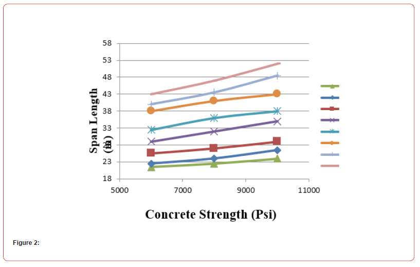
Comparison graph of concrete strength vs span length
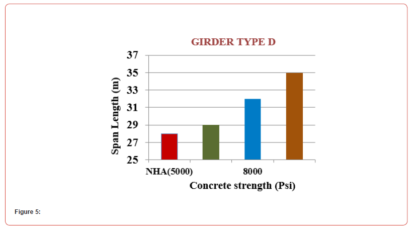
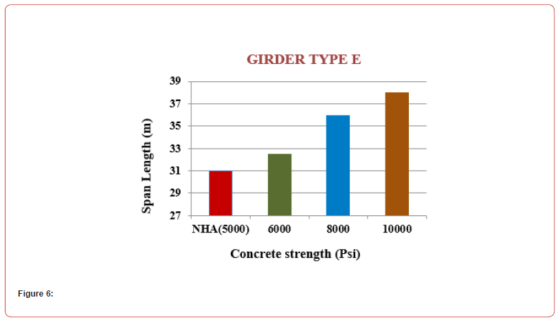
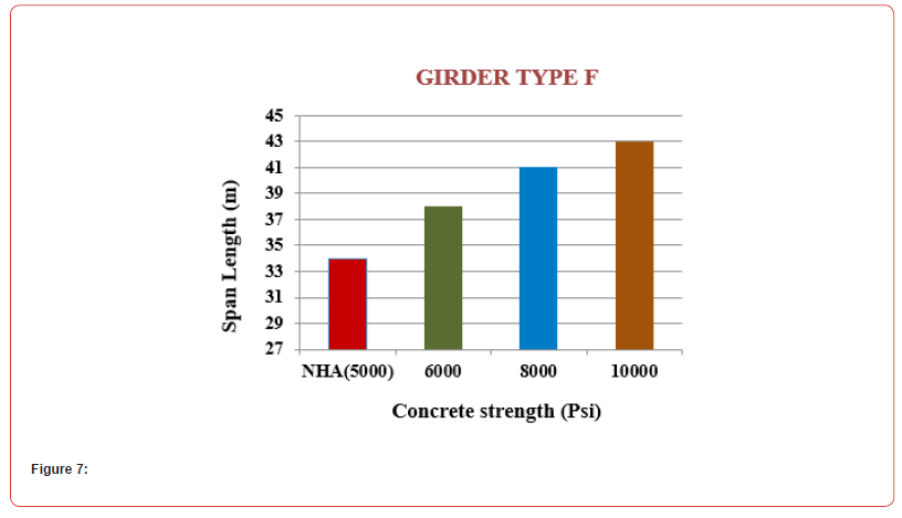
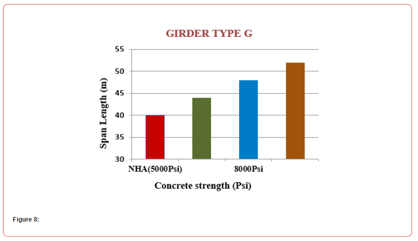
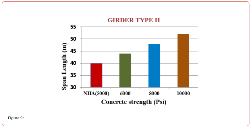
The above graph shows the comparison of concrete strength with span of girders. All the eight types of NHA girders are designed and from these results it can be concluded that when we increase the concrete strength from 6000 Psi to 8000 Psi, the spans for all these girders increases. All the types of girders have similar behaviour for the increase in concrete
Effect of Concrete Strength on Span of Girders
By increasing specified concrete compressive strengths (fc‘)
from 6000 Psi to 10000 Psi, the following results are observed:
For girder spacing 2.5m center to center and the average increase
in span length is 25 %.
a. For Type A girder of NHA, by increasing concrete strength from
6000 Psi to 10000 Psi the increase in span length is up to 22.5
%.
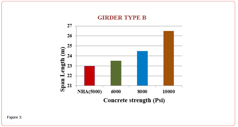
b. For Type B girder of NHA, by increasing concrete strength from
6000 Psi to 10000 Psi the increase in span length is up to 21 %.
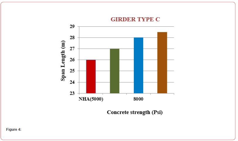
c. For Type C girder of NHA, by increasing concrete strength from
6000 Psi to 10000 Psi the increase in span length is up to 20 %.
d. For Type D girder of NHA, by increasing concrete strength from
6000 Psi to 10000 Psi the increase in span length is up to 25 %.
e. For Type E girder of NHA, by increasing concrete strength from
6000 Psi to 10000 Psi the increase in span length is up to 22.5
%.
f. For Type F girder of NHA, by increasing concrete strength from
6000 Psi to 10000 Psi the increase in span length is up to 26.5
%.
g. For Type G girder of NHA, by increasing concrete strength from
6000 Psi to 10000 Psi the increase in span length is up to 31 %.
h. For Type H girder of NHA, by increasing concrete strength from
6000 Psi to 10000 Psi the increase in span length is up to 30 %.
From these results it is obvious that that by increasing concrete strength of girders the span length increases for all the eight types of girders .The maximum increase in span range is for girder “Type G” i.e. 31%.According to NHA the span range specified is from 29m to 37m, concrete strength used is 5000 Psi and the depth of the section is 2400mm.But if we use high strength concrete from 6000 Psi to 10000 Psi the same girder depth of NHA can be use for span length up to 48.5m. It is more economical to use shallower girder cross section of HSC than to use deeper cross section of NSC. It means that if we fix the span of girder, then it is more economical to use shallow section using high strength concrete for same girder length than to use deeper section when we use normal strength concrete. When uses high strength concrete in girders, the span length range increases. Due to increase in span, the substructure requirements like pier, pile cap and no of pile reduces and hence overall cost of bridge reduces because of lighter superstructure. Also in our daily dealings if we have to interact with a site here due to strata conditions or due to some geographical factors we have to avoid pier/pile in our structure then in such circumstances it is more beneficial; to use high strength concrete in structure to get longer span and at the same time overall cost of bridge reduces.
-
Mehwish Mustafa* and Afzal Javed. Effect of Concrete Strength on the Design of Prestressed Concrete Bridge Girders. Cur Trends Civil & Struct Eng. 11(4): 2025. CTCSE.MS.ID.000766.
-
: Concrete strength; bridge girders; prestressed concrete; concrete strength; hanging bridge; steel frame bridge; Iris Publishers; Iris Publishers Group
-

This work is licensed under a Creative Commons Attribution-NonCommercial 4.0 International License.


