 Research Article
Capsizing Mechanism of Self-Elevating Platform Based on Structural Stability Theory
Shouji Toma1,2* and Wai Fah Chen3
1Emeritus Prof., Hokkai-Gakuen University, Japan
2Taiki Consultant, Inc., Sapporo Office, Japan
3Emeritus Professor., University of Hawaii, USA
Shouji Toma, Emeritus Prof., Hokkai-Gakuen University, Japan
Received Date:December 03, 2024; Published Date:December 16, 2024
Abstract
At Okinotorishima, a self-elevating platform (SEP) to be used as a pier after installed permanently on the sea bed capsized while in transit as a buoyant body in March, 2014. The structural characteristics of SEP include a very high center of gravity due to its long legs and a large rectangular hull as used for a working platform, resulting in a shallow draft, which significantly differs from conventional vessels and causes unstable status.Usually, the stability of a buoyant body is evaluated using metacentric height and restoring moment curves based on ship algorithms. However, here the floating stability is examined by the structural stability theory, which is commonly used to address overturning problems of land base machinery with high center of gravity such as pile drivers or cranes on soft foundation. To this end, a capsizing experiment using floating models of SEP was conducted and the results showed that the critical loads obtained from the experiments closely aligned with structural stability analysis. In this paper, the capsizing mechanisms of the SEP of Okinotorishima are speculated from a view point of structural stability theory. Furthermore, the stability criteria for top-heavy floating bodies like SEP are developed by combining ship algorithms with structural stability theory.
Keywords:Self-Elevating Platform; Floating Stability; Pile Driver Overturning; Overturning Mechanism; Structural Stability, Soft Foundation
Introduction
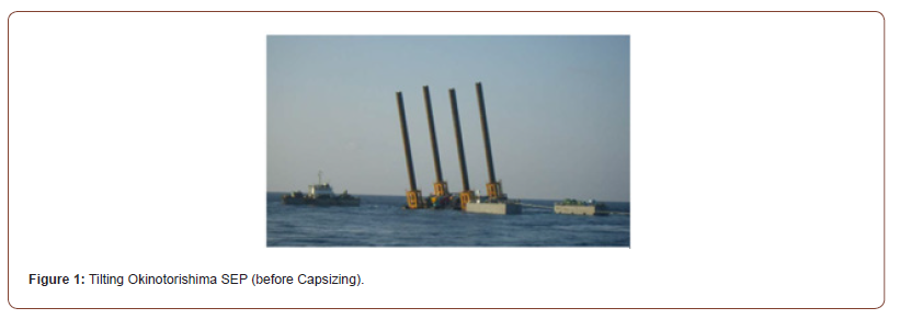
A self-elevating platform (hereinafter referred to as SEP) overturned while in the process of surfacing and moving at the site of Okinotorishima on March 30, 2014 [1]. Figure 1 illustrates the SEP of Okinotorishima at the construction site, showing its inclination prior to capsizing. The SEP is designed to serve as a part of permanent pier after being jacked onto the seabed at the location. Its structural features significantly differ from those of conventional vessels, including a high center of gravity due to its four long legs and a large rectangular hull intended for use as a working platform, which results in a shallow draft. The stability of floating bodies is typically evaluated using metacentric height and restoring moment curves derived from conventional ship algorithms. However, there have been proposals to modify these algorithms to incorporate factors related to the height of the center of gravity height in stability indices for top-heavy structures like SEP [2].
In this paper, an evaluation method based on structural stability theory, which offers a different perspective from traditional ship algorithms, is explored. Structural stability theory refers to the concept that a structure’s deformation cannot return to its original state due to instability within the structural system; for floating bodies, this results in capsizing. A classic example of structural instability is the buckling of long columns. The author has conducted research on overturning accidents involving various top-heavy machinery, such as pile drivers, cranes and jacks. Given that buoyant bodies with a high center of gravity, like the SEP, exhibit similar overturning mechanisms to those of pile drivers and other machinery, this paper examines the feasibility of applying the same analytical model and approach to this scenario.
Capsizing of Okinotorishima SEP
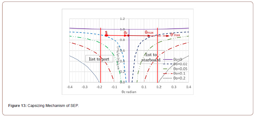
Table 1 shows the timeline leading up to the capsizing as described in the accident report of the Okinotorishima SEP [1]. According to this table, the SEP (used as a permanent pier after installation) capsized shortly after being towed out from the transport ship. The cause is attributed to downward force generated by the current and the rotational energy from waves exceeding the dynamic restoring moment. It was also reported that due to moving the crane on the SEP there was oscillating phenomenon before capsizing, which suggested dynamic effects were contributed. This capsizing mechanism will be inferred later in Figure 13.
Table 1:Capsizing Process of the SEP.
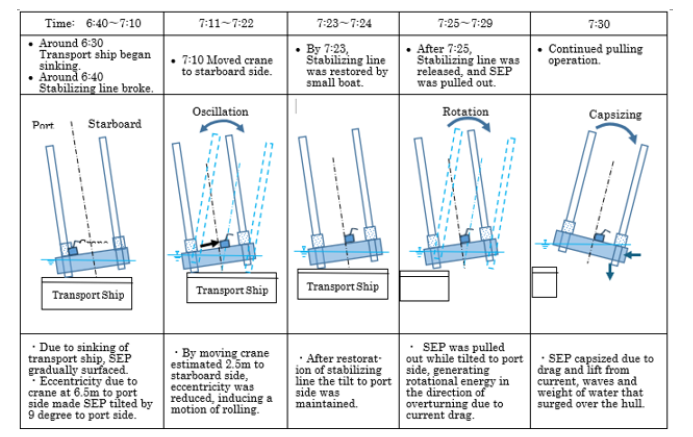
(Remark: This table is cited from Ref. 1 [1])
Structural Stability Analysis (Static)
Analytical Model and Critical Load
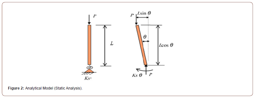
In structural stability theory applied to the overturning issues of pile drivers and other onshore heavy machinery, the overturning mechanisms are classified into “moment type of overturning” and “structural instability type” [3]. The structural instability category is further divided into “buckling type of overturning” and “equilibrium transition overturning.” In the moment type of overturning mechanism, toppling occurs when the overturning moment due to external forces and gravity exceeds the resisting moment at the support on “solid” foundation. On the other hand, the structural instability type of overturning occurs when supported on “soft” foundation. There, the structural model of the onshore heavy machinery such as pile driver on soft ground are simplified to a rigid bar-rotational spring structural system as shown in Figure 2. Specifically, the machine is assumed to be a rigid body of height (L), with a load (P) acting on upper end, while the lower end is supported by a rotational spring to cope with the soft foundation. This structural system has been used to evaluate the stability of onshore machinery [3-7] and will be applied here to investigate the floating stability of SEP.
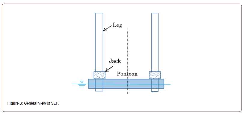
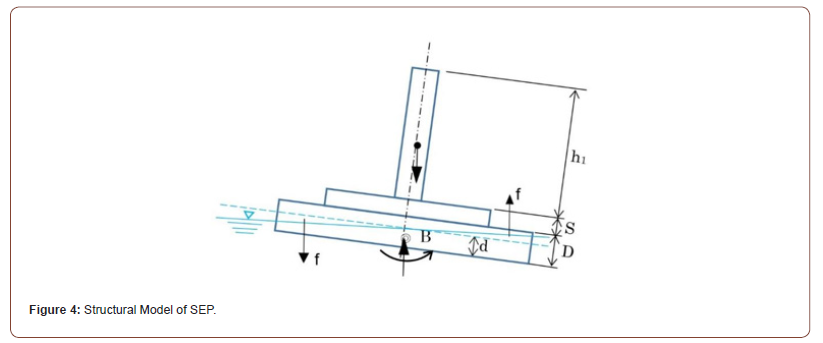
Weight distribution of SEP consists of mainly three parts: hull (pontoon), legs and payloads including jacks as seen in Figure 3. In static stability, this structure is simplified to a structural model in Figure 4, in which four legs are put together in one leg. This structure model was used in the model experiments, and there further simplified in evaluating the results into the same rigid bar-rotational spring system as shown in Figure 2 [8]. This structural system in Figure 2 has a critical load (Pcr) determined by Eq. (1), at which the bar (machine) possibly overturns without any overturning moment, similar to how a long column can bend without any bending moment due to elastic buckling [9].

in which Ks =rotational spring stiffness, Lcr=critical (limit) heigh
This critical (stability limit) load relates to metacentric height (GM) in ship algorithms as explained later.
Rotational Spring Stiffness
In order to derive the rotational spring stiffness (Ks) in Eq. (1), the structural model in Figure 4 is considered [8]. In the figure, four legs are put together in one central pole; this simplification will not cause any contradiction in static analysis because only the first order moment is concerned to determine the center of a whole gravity. From the buoyancy difference (f) between left and right sides, the righting moment (MR) is calculated as follows [8]:

in which b =width of pontoon (hull), l =length of pontoon (hull), θ =inclination angle
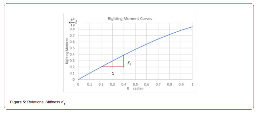
Here, assuming the water density is 1g/cm3, the buoyant force will be equal to the water volume displaced by the hull. Equation (2) is plotted in Figure 5, and disregarding the height of freeboard, the righting moment continues to increase and the curve keeps rising. Taking sinθ≈θ for small θ, the rotational spring stiffness (Ks) can be obtained from the definition shown in Figure 5 and Eq. (2) as follows:

in which Iy = moment of inertia of the water line area with respect to long axis of pontoon
It is interesting to know that the rotational spring stiffness (Ks) is equivalent to the moment of inertia of the water line area (Iy). In ordinary vessels the center of buoyancy shifts with incline, causing a variation in (Iy). However, it is assumed that in structural stability theory, the center of buoyancy remains fixed and Iy is constant.
Model overturning experiments of SEP as a buoyant body were performed using the structural model shown in Figure 4 [8]. The experimental results were analyzed by using structural model shown in Figure 2, and showed that the critical load obtained from the experiment closely matched the results from structural stability analysis of Eq. (1), confirming a similarity between structural stability theory and ship algorithms. The error between the experiment and the theory was within 5% with the average 2%.
Relationship between Structural Stability and Ship Algorithms
In ship algorithms, stability concerning the weight (load) is determined by the metacentric height (GM), which is expressed by the following Eq. (4) [8].

in which V =displaced volume (=total weight of SEP), Gt = height of gravity center from hull bottom, d =draft depth.
Considering the relations Ks= Iy in Eq. (4) and V = Wt , Eq. (4) becomes

in which Lcr =critical height of gravity center given by Eq. (1), Lact =actual height of gravity center.
Equation (5) gives the relationship between ship algorithms and structural stability theory for floating structures. It can be seen from Eq. (5) that the metacentric height (GM) is the difference between the critical and actual heights of the loads, namely GM is the margin of stability by the load heights. This relationship is illustrated in Figures 6 & 7, describing the structural models based on ship algorithms and structural stability theory, respectively. Each mark in Figure 6 implies that B and B’ are buoyancy centers, G is gravity center and M is metacenter.
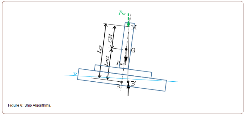
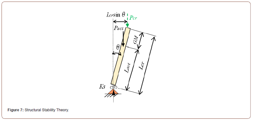
Equation (5) can be transformed into the following two equations:

The above two equations express the relationship of the ship stability algorithms in the first term and the structural stability theory in the second term in non-dimensional form. Equations (6) and (7) are equivalent because the ratios Lact/Lcr and Pact/Pcr have the same value. There, Lact and Pact are the actual values of SEP and Lcr and Pcr are the critical (limit) values calculated from Eq. (1). Nondimensional form enables to compare different types of floating structures between such as SEP and ordinary vessels. On the other hand, the metacentric height (GM) in ship algorithms is expressed by dimensional height, therefore difficult to compare between structurally different types of floating bodies.
The overturning of pile drivers and cranes usually occurs on weak ground, making it difficult to grasp the relationship between ground bearing capacity and rotational spring stiffness (Ks). However, in the case of buoyant bodies’ stability, the righting moment due to buoyancy is relatively clear, making it easier to determine the rotational spring stiffness, which is a concern in structural stability theory to evaluate its applicability. Therefore, the research results presented here not only address the issue of rotational stiffness but also serve as validation for papers dealing with overturning problems of onshore heavy machinery [3-7]. This includes development of the safety criteria of SEP and understanding of the overturning mechanism of the Okinotorishima SEP from the perspective of structural stability theory.
Structural Stability Analysis (Dynamic)
Analytical Model
Figure 8 schematically illustrates the structural model of SEP in dynamic analysis (cf. Figure 2). This model for dynamic analysis is first applied for structural stability analysis of overturning of onshore machinery such as pile drivers, cranes and jacks [5]. Differently from the model in static analysis shown in Figure 2 or 7, the mass is divided into three parts: “M0” for hull, “m” for legs and “M1” for payload of equipment including jacks as shown in Figure 8. This is because in dynamic analysis the moment of inertia (second order moment) is involved, therefore distances from the support point to the masses are desired to be exact. On the other hand, this is not required in static analysis as far as the gravity center of whole mass matches to the sum of each part, because only the first order moment is considered. Accordingly, height of the gravity center of total weight, denoted by Gt in Figure 8, is equivalent to the load height L in Figure 2.
Equations of Motion
The structural model represented in Figure 8 oscillates freely when the initial condition of the inclination angle 0θ is given andreleased instantaneously. Using the structural model in Figure 8, the time variation of the inclination angle θ(t) is given by the following equation of motion if there is no damping and no initial angular frequency of oscillation [5].

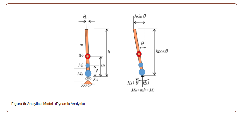
where the oscillation center (θc) and the amplitude (θc −θ0 ) are

in which θ0=initial inclination angle, θc=central angle of oscillation, Pcr=critical load in Eq. (1), Pact =actual load (=total weight Wt for SEP).
The natural angular frequency of oscillation (ω) is expressed by

in which Q =first order moment with respect to buoyancy center, I =second order moment with respect to buoyancy center, Ks =rotational spring stiffness.
Using Eq. (9), relations between the load ( Pact/Pcr) and the central angle of oscillation (θc) are plotted for different initial inclination θ0 in Figure 9 [5]. It should be noted that the curves in Figure 9 are the same as load-deflection curves obtained from the equilibrium equation of forces for varying the initial inclination angles in static analysis [6]. The stability limit angle (θu) in Figure 9 indicates the critical inclination angle (stability limit angle) at which SEP will lose the restoring moment (capsizing). The stability limit angle can be determined from the curves of the restoring moment with the inclination angle as explained later (see Figure 11). Figure 9 also shows the amplitude of oscillation (θc-θu) for SEP with the initial inclination angle θ0=0.05 and two load cases: Pact/Pcr =0.6 (green line) and 0.35 (red line) when the inclination of SEP increases from θ0=0.05 to each θc instantaneously by some reason. In these cases, the green line (Pact/Pcr =0.6) oscillates within the stability range, however, as seen in the red line (Pact/Pcr =0.35), when the maximum inclination exceeds the stability limit, SEP will capsize. This process is discussed in more detail in Ref. 6 [6].
When the initial angular frequency of oscillation is not zero, i.e., ω0 ≠ 0 , the equation of motion Eq. (8) becomes as follows [5]:

where the phase difference δ is expressed by

Obviously, the amplitude of oscillation in Eq. (12) is larger than the case without the initial angular frequency of oscillation in Eq. (8). In capsizing accident of the Okinotorishima SEP, this effect might have contributed.
Capsizing Scenario of Okinotorishima SEP
Natural Period of Oscillation (Dynamic Analysis)
According to the accident report [1], it is stated that the SEP was rolling with the period about 90 to 100 seconds before capsizing. Therefore, in this section the natural period of oscillation is examined to speculate the capsizing process through Eq. (11) in dynamic analysis of structural stability theory. Table 2 and Figure 10 show the parameters including dimensions and weights of each part of the SEP. In the calculations in Table 2, the first order moment is determined using the total weight Wt (ton-f) and the center of gravity, while the inertia moment (second-order) is calculated by classifying three mass components which are hull M0(ton), legs m (ton/m), and onboard equipment (payload) M1(ton) as shown in Figure 8. It is important to notice the difference in units between the inertia moment (ton-m2) and the gravity moment (ton-f-m) in Table 2, in which the acceleration of gravity f=9.8m/sec.2 is used.
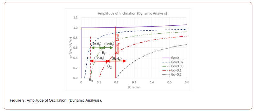
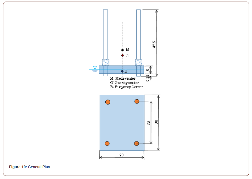
Table 2:Natural Frequency of SEP.
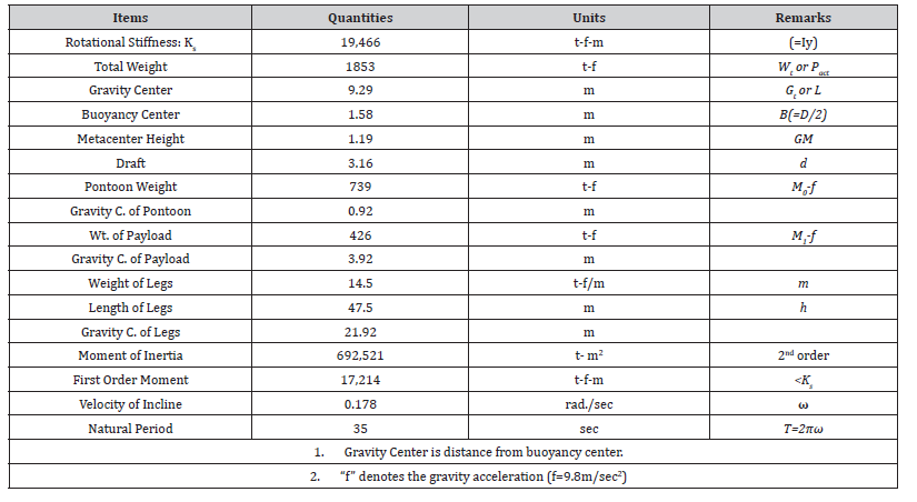
Based on the data in Table 2 and the structural model in Figure 8, the natural angular frequency of oscillation of the SEP (ω) is calculated from Eq. (11), yielding a value of 0.178rad./sec. as seen in Table 2. When this natural angular frequency is used to determine the natural period of oscillation, it results in a value of 35sec., which is considerably shorter than the measured value of 90 to 100sec. in the accident report [1]. It seems that this tendency is likely due to the simplifications made in the actual SEP on the sea with the structural model shown in Figure 8. Specifically, while the support point is represented merely as rotational spring based on buoyancy differentials, the actual rectangular hull rotation involves additional factors, such as the dynamic resistance of water by waves and current flow.
Restoring Moment and Stability Limit Angle (Static Analysis)
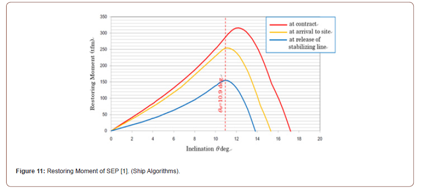
Figure 11 presents the restoring moment curves of the Okinotorishima SEP, derived using ship algorithms [1]. It serves as the stability diagram of the SEP, illustrating the relationship between the restoring moment (MS) and the displacement inclination (θ) up to the point where the restoring moment vanishes. Three curves in the figure indicate from above at the time of construction order (contract), upon arrival at the site and at the time of release of fixation from tippling, respectively. The restoring moment (MS) is a difference of two main components, i.e., MS=MB−MG, where the buoyancy moment MB (or righting moment MR) is created by buoyancy, and the overturning moment (or gravity moment) is generated by gravity. Referring Figure 6 in ship algorithms, the restoring moment MS can also be expressed by MS =Pact GM sinθ.Here, the distinction between “restoring moment MS” and “righting moment MR” moments should be noticed.
In structural stability theory, the stability limit angle (or toppling inclination angle) θu is used as the critical angle at which further inclination becomes unstable (toppling). From Figure 11, it can be observed that the restoring moment decreases sharply after reaching its maximum value, which is significantly different from the gradual decrease seen in typical ships. In such cases, it is possible that the structure may become unstable due to dynamic inertial forces after the restoring moment reaches its maximum value. Thus, for safety, the inclination angle at which the restoring moment reaches its maximum is defined here as the stability limit angle (θu). When viewed in Figure 11, this corresponds to the point that tangential angle of the curves is zero at which the restoring moment begins to decline and is found that the stability limit angle (θu) of the SEP is 10.9deg. (0.19rad.).
In structural stability theory, referring to the analytical model in Figure 2, the equilibrium equation in static analysis becomes

The first term of Eq. (14) is the righting moment due to spring support and the second is overturning moment due to load gravity. The elastic buckling equation Eq. (1) is derived from this Eq. (14), therefore the critical load (Pcr) and the critical height (Lcr) come from this Eq. (14) [9]. Using the actual values for load, the restoring moment MS in structural stability theory is a difference between the two terms of Eq. (14) as follows:

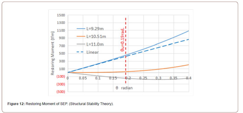
The righting moment due to buoyancy can be expressed by MR = Ksθ induced by a rotational spring, which corresponds to the buoyancy moment (MB) in ship algorithms. Equation (15) is plotted in Figure 12 in which three cases are shown for L=9.29m< Lcr , L=10.5m= Lcr and L=11.0> Lcr in which Lcr is the critical (neutral) value obtained from Eq. (1). For reference, the dotted linear lines in Figure 12 express the initial stiffness (Ks) of the restoring moment curves, which are Ks > 0 for L< Lcr , Ks = 0 for L= Lcr , and Ks < 0 for L > Lcr in structural stability theory and correspondingly equivalent to GM > 0, GM = 0 and GM < 0 in ship algorithms, respectively.
The restoring curves of ship algorithms in Figure 11 increase until the critical inclination angle (θu) (stable), then decline (unstable). On the other hand, the restoring curves of structural stability theory in Figure 12 continue to increase indefinitely because it is ignored that the draft exceeds the freeboard due to the tilt of the SEP. Therefore, while the critical inclination angle (θu) can be determined from the restoring moment diagram of Figure 11 based on ship algorithms, it cannot be determined by the curves in Figure 12 based on structural stability theory.
Capsizing Mechanism (Dynamic Analysis)
The capsizing process of the Okinotorishima SEP is described in Table 1, which attributes the cause of the overturning to rotational energy from external forces, such as current flow and waves, exceeding the restoring force [1]. Here, an analysis from the perspective of structural stability theory will be considered as an alternative approach. Load-displacement angle curves are presented previously in Figure 9, which expresses static equilibrium state [6]. Each curve in the figure represents the change of displacement angle as the load increases for different initial inclination angle, i.e., the initial angle when the load is zero. It is found that this static equilibrium curve serves as the center of oscillation (θc) in Eq. (8) of dynamic analysis [5]. Namely, if there is no damping, the oscillation amplitude due to inertial force will be equal to the amount of change between the start angle and the central angle of oscillation (θc −θ0).
Based on this premise, let us infer the overturning process of the SEP using Figure 13. The load-displacement inclination angle curves in Figure 13 are the same as those in Figure 9, but expresses the center of oscillation here in dynamic analysis and symmetrical to both sides. According to Table 1 cited from the accident report [1], in the overturning process of the SEP (with the load P/Pcr=0.886), it was initially held at an inclination of approximately 9deg. (0.16rad.) to the port side, due to eccentricity of the gravity, the restraining line and contact with the barge deck. This initial state is indicated by Point S in Figure 13. When the SEP was pulled away from the barge, it lost those restraining forces, causing a loss of balance and an attempt to shift to a new equilibrium state, i.e., the center of oscillation (θc), in Figure 13. The accident report said that this shift was toward a port-side inclination of θc =1.6deg [1].
In this process, as explained in Figure 9, due to inertial force, it continued past the equilibrium point θc and inclined to the maximum oscillation angle with the amplitude (θc −θ0) on the starboard side, marked as θmax. At the start of this oscillation, due to the loss of restraining force along with external factors of waves and current flow as mentioned in the accident report, the initial angle frequency ω0 arose and likely amplified the oscillation width. This might have caused to exceed the stability limit angle θu (=0.19rad. or 10.9deg.) and inclined further up to θ’max as indicated by the dotted arrow line in Figure 13, ultimately leading to capsizing.
In this way, structural stability theory can apply dynamic analysis to assess stability of SEP whereas the ship algorithms are based fundamentally on static analysis which cannot treat a dynamic oscillation. The influence of inertial forces captured through dynamic analysis in structural stability theory may help to understand better the capsizing behavior of SEP.
Considerations from Free Oscillation
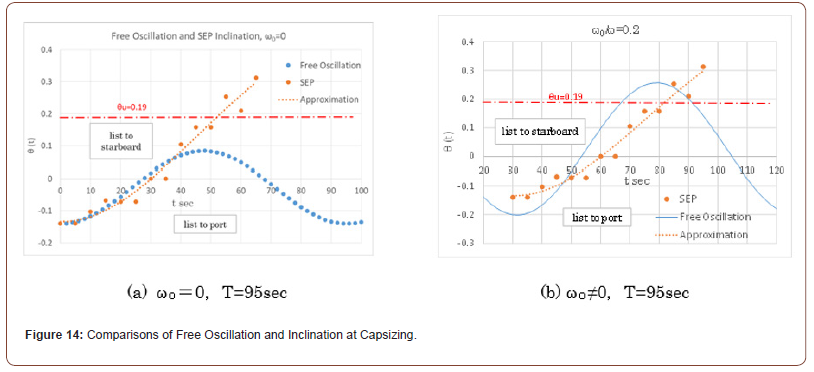
This section examines the capsizing behaviors of the SEP through free oscillation in dynamic analysis. It was reported that the SEP was oscillating with the period 90 to 100sec. just before capsizing [1]. Then, taking the period 95sec. in Eqs. (8) and (12), Figure 14 (a) and (b) illustrate the temporal variations in the tilt angle of the SEP during free oscillation for the cases with and without the initial angular velocity (ω0) by blue dots, respectively. The stability limit angle at which the SEP becomes unstable, i.e., θu=10.9deg. (0.19rad.), is indicated by a dot-dashed horizontal line. In the figures, the observed inclination angles at the capsizing accident are plotted by red dots for comparison [1].
According to the accident report [1], before the capsizing occurred, the SEP was pulled away from the barge (transport ship), resulting in a tilt angle of approximately 9deg. (0.14rad.) to the port side as seen in Table 1 and Figure 13. This angle is used as the initial tilt angle θ0 in calculating the curves in Figure 14. Here in dynamic analysis, the static equilibrium angle at that moment, reported as 1.6deg. (0.0279rad.), is taken as the center angle of oscillation (θc).
It can be seen that the theoretical inclination curve (the blue dotted line) without initial angular velocity ω0 =0 in Figure 14(a) does not reach the capsizing angle θu, while the theoretical inclination curve with initial angular velocity ω0 ≠0 in Figure 14(b) exceeds the capsizing angle. From Figure 14(a), it is found that the observed tilt angle during the SEP capsizing incident expressed by red dots closely matches the initial portion of behaviors predicted by free oscillation analysis.
Then, Figure 14(b) shows the case where the initial angular frequency arises by some reason; assuming a value of ω0/ω =0.2, Eq. (12) is plotted. In this case, the amplitude increases, exceeding the stability limit angle (θu) and resulting in capsizing. The cause of an initial tilt angle frequency may include various factors, such as the influence of waves and current flow, the pulling force of tugboat ropes or their release, and contact between the SEP base and barge surface. Additionally, as mentioned previously, it is necessary to consider that simplifying the legs from four to one in the structural model of Figure 8 could lead to an underestimation of inertial forces. This capsizing mechanism seems to agree with the behavior in Figure 13. It should be noted that the theoretical oscillation curve in Figure 14(b) represents only a portion of the curve calculated from Eq. (12). Despite the various assumptions and simplifications, it can be inferred that the free oscillation behavior in structural stability theory is related to the capsizing factors of the SEP.
Stability Criteria
Load Criteria Static Analysis
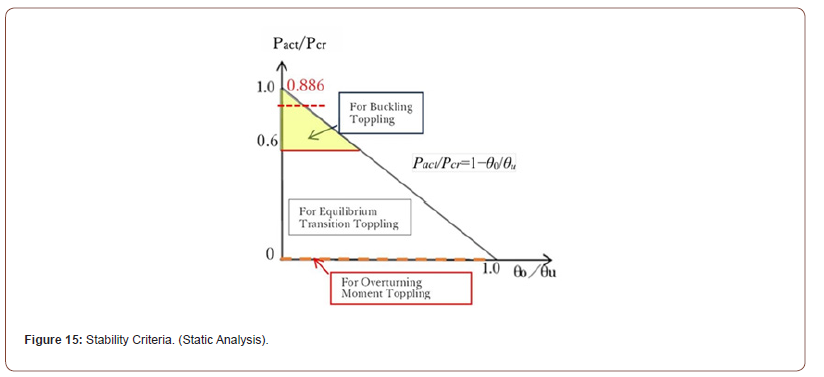
This section describes the stability criteria of safety for SEP. If the structural model shown in Figure 2, which is used in static analysis for pile drivers, etc., is applicable to SEP, then the stability criteria shown in Figure 15 for pile drivers, etc., may also be applied to assess SEP stability. There, the conditions of toppling are derived as represented below by Eqs. (16) and (17) [7].

in which θ0=initial inclination angle without loading (see Figure 2),θu=critical inclination angle defined in Figure 11.
In Figure 15, the triangle area surrounded by the axes and the diagonal line, which is expressed by Eq. (16), means no-toppling theoretically. The criteria for load, Eq. (16), and for height of gravity center, Eq. (17), are actually equivalent. In order not to capsize, relation between the load and displacement angle must be within the triangle region of Figure 15. As the weight of floating body on the vertical axis increases, structural stability decreases. Therefore, the upper colored area (yellow) is considered to have a poor stability and should avoid in the design. Here, just for an example, safety threshold of Pact/Pcr =0.6 is set based on a study of pile drivers, etc. [7]. When a floating body with a high center of gravity, like SEP, is plotted on Figure 15 according to Eq. (16) or (17), it tends to fall into the unstable upper area of the vertical axis (Pact/Pcr ). For an example of the Okinotorishima SEP, the load value is calculated from Table 2 as Pact/Pcr=0.886, which is positioned quite high as shown in Figure 15. The initial inclination limit of capsizing (θ0/θu) in this case is calculated to 0.114, which gives a permissible initial inclination as θ0 =0.114x10.9deg.=1.24deg. which is quite low. In contrast, a conventional vessel is generally positioned closer to the center, where stability is higher. With a low center of gravity, a typical vessel has greater stability, placing it near the horizontal axis in Figure 15.
In the case of a floating structure, since the supporting base is water, the rotational spring cannot be rigid. Therefore, in the case of SEP which is supported by a finite rotational spring, stability must be evaluated using both perspectives of the limit load (or height) by structural stability theory on the vertical axis and the stability limit angle (θu) by ship algorithms on the horizontal axis. This approach involves considering “equilibrium transition type” of overturning as described in the toppling mechanisms of onshore machinery through the application of structural stability theory [3,6]. The equilibrium transition type of toppling is located in the middle range of the stability criteria diagram shown in Figure 15.
Dynamic Analysis
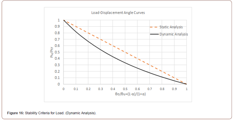
In dynamic analysis, the stability criteria for onshore machinery such as pile drivers, cranes, etc., on soft foundation are studied and the result is shown by the solid line in Figure 16 [7]. The dotted line in Figure 16 is the criteria by static analysis, which is the same as that in Figure 15. Comparing the static and dynamic analyses, the stability range in dynamic analysis becomes narrower than static analysis. It can be seen from Figure 16 that in the case of Okinotorishima SEP, the initial inclination angle of capsizing is very small because of high load level.
It is obvious that the dynamic effect by inertial force due to oscillation reduces floating stability. It should be noticed that since the results in Figure 16 are based on on-land structures and in the cases of floating structures like SEP on the sea, the influence of inertial forces due to waves and current flow seems greater, it is likely that stability conditions will become even stricter than those indicated in Figure 16.
Stability Criteria for SEP
By using the stability condition of Eq. (17) and the metacentric height of Eq. (6), the following equation Eq. (18) for stability criteria of floating bodies including SEP can be derived.

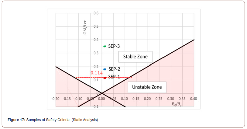
Note that both Eqs. (17) and (6) are derived by static analysis, thus Eq. (18) is static as well. The stability condition given by Eq. (18) is illustrated in Figure 17. The vertical axis represents GM/Lcr , which are determined by both ship algorithm and structural stability theory, and the horizontal axis shows the dimensionless tilt angle of the floating body symmetrically to both port and starboard sides. A negative value of GM indicates instability when the actual load of SEP (Pact) exceeds the critical load (Pcr). From Figure 17, it can be seen that the greater the value on the vertical axis (GM/Lcr) and the smaller the initial tilt angle on the horizontal axis (θ0/θu), the higher the stability. The stability condition equations, Eqs. (16) and (17), based on static analysis of structural stability theory are equivalent to the stability condition equation, Eq. (18). Therefore, Figure 17 is equivalent to Figure 15, but the two figures are shaped inversely. Additionally, a safety factor required in the practical design is not considered in those figures and needs to be investigated in the future.
Conventional ships normally have a relatively large stability (limit angle) along with a large limit load and metacentric height. However, SEP has a smaller stability limit angle, making them more susceptible to instability from the critical load. The metacentric height (GM) represents the safety margin against the critical load (see Eq. (5)), which is reflected on the vertical axis in Figure 17. Therefore, the stability evaluation by the metacenter corresponds to the buckling type of overturning mechanism in structural stability theory, where the capsize is determined by whether the load exceeds the stability limit load [3]. For floating structures with structural characteristics like SEP, it is essential to consider both the critical load Pcr (capsize load) and the stability limit angle θu (capsize angle) to accurately assess stability. Accordingly, a stability assessment based on the “equilibrium transition type” of toppling mechanism proposed in the previous studies is considered applicable for SEP [3-7].
Stability of Okinotorishima SEP
In case of the Okinotorishima SEP, it has been reported that payloads were added at the construction site, increasing the total weight [1]. Had these extra loads not been added, the total load value Pact/Pcr =.886 on the vertical axis in Figure 15 would be smaller and GM would be larger in Figure 17, then the SEP is tending towards stability. Figure 17 shows three loading samples regarding the stability level of the SEP: SEP-1 uses the total weight in Table 2 which is the case at capsizing, SEP-2 represents the case with the payload weight removed, and SEP-3 is a further modification of SEP-2 with the center of gravity of the legs lowered by 5 meters [1]. At this point, the initial tilt angle is set to a small value of θ0/ θu=0.01rad. It should be noted that the observed tilt angle of the SEP before free oscillation started was about 9deg., placing it in a dangerous range comparing to θu=10.9deg.
From Figure 17, it can be found that as GM values on the vertical axis increase, stability against capsizing increases proportionally. Comparing SEP-1, SEP-2 and SEP-3 in Figure 17, a stability safety can be assessed more precisely with numerical values. Thus, by using the stability criteria diagram of Figure 17, SEP stability can be evaluated not only by GM values in ship algorithms but also by both load and displacement angle provided by the theory of structural stability.
Conclusion
The self-elevating platform (SEP) possesses unique characteristics, including a high center of gravity resulting from its long legs and a rectangular hull, which differentiate it from conventional vessels. These features raise concerns about the applicability of traditional ship stability assessment methods to SEP. This study aims to evaluate the stability of SEP from the perspective of structural stability theory, which diverges from maritime stability approaches, and assesses its suitability for application. Structural stability theory has previously been proposed to address toppling issues in land-based structures on soft ground, such as pile drivers and cranes [3-7]. In this paper, the same analytical approach is applied to the stability of the floating body of SEP.
To achieve this, a model experiment was conducted, and the results were compared with theoretical values derived from structural stability theory [8]. The findings indicated that the error was within 5% (average 2%), demonstrating adequate applicability. Furthermore, the study addressed the challenge of rotational spring stiffness, which had been a significant issue in the toppling stability of pile drivers and cranes. The floating body model experiment allowed for a clear determination of this rotational stiffness through the righting moment provided by buoyancy, thereby confirming the validity of previous analytical methods used for pile drivers and cranes [3-7].
Traditional ship algorithms can accommodate complex hull shapes and account for the shifting center of buoyancy as the vessel tilts. In contrast, structural stability theory assumes a fixed center of buoyancy, treating it as a stationary support point (rotation center). Consequently, while ship algorithms exhibit a nonlinear increase in righting moment with increased tilt, structural stability theory assumes a linear (constant) increase. This assumption presents limitations for structural stability theory; however, for simple rectangular hulls like SEP, the error is considered minimal.
Based on these observations, the relationship between ship
algorithms and structural stability theory can be summarized as
follows:
a. In ship algorithms, the metacentric height (GM) is calculated
by assuming that the center of buoyancy moves, whereas in
structural stability theory, it is treated as a fixed support point.
Despite this difference, both approaches are essentially the
same from the perspective of static analysis.
b. The metacentric height (GM) in ship algorithms is evaluated as
a dimensional value, whereas the stability index in structural
stability theory is assessed with dimensionless values (Lact/
Lcr or Pact/Pcr), enabling comparisons between floating bodies
with different structural forms.
c. The metacentric height (GM) in ship algorithms serves as
a safety index against the critical height (Lcr) in structural
stability theory, indicating that the stability assessment by GM
resembles the “buckling overturning type” of mechanism in
structural stability theory [3].
d. In ship algorithms, the angle of inclination at which the
restoring moment is maximized corresponds to the stability
limit angle (θu) in structural stability theory; exceeding this
angle results in capsizing.
e. The righting moment due to buoyancy in ship algorithms (MB)
is equivalent to the righting moment (Ksθ) induced by the
rotational spring in structural stability theory.
f. The stability criteria of floating bodies can be expressed
by the following equation, Eq. (18), which aligns with the
“equilibrium transition type” of overturning mechanism in
structural stability theory [7].

Finally, it is important to note that research applying structural stability theory to overturning problems has been limited, and the perspectives presented here have not yet been thoroughly verified. Further extensive research in this area is anticipated.
References
- Interim Report of Capsizing Accident of Okinotorishima Self-Elevating Platform (2014) Port/Aviation Department, Kanto Regional Development Bureau, Ministry of Land, Infrastructure, Transport and Tourism (MLIT) (in Japanese).
- Doya Y, Sawada T (2021) Stability Index for Rectangular-Hulled Floating Bodies. Journal of the Japan Society of Naval Architects and Ocean Engineers 33: 63-72.
- Toma S, Chen WF (2022) Overturning Mechanisms of Jacks, Cranes and Pile Driving Machines. Structural Engineering International (SEI), Taylor & Francis Online.
- Toma S, Chen WF (2022) Some Aspects of Overturning Mechanisms of Pile Driving Machine on Soft Foundation. American Journal of Civil Engineering 10(6): 225-232.
- Toma S, Seto K, Chen WF (2023) Dynamic Analysis for Overturning of Pile Driving Machine on Soft Ground. Transactions on Engineering and Computer Sciences 11(2): 61-81.
- Toma S, Seto K, Chen WF (2024) Comparisons of Static and Dynamic Analyses on Toppling Behaviors of Pile Driving Machinery, etc., on Soft Foundation. Archives of Advanced Engineering Science 2(3): 150-159,
- Toma S, Chen WF (2024) A Study on Safety Criteria for Toppling of Pile Drivers and Cranes Based on Structural Stability. Archives of Advanced Engineering Science.
- Toma S (2024) Model Experiments for Floating Stability of Self-Elevating Platform and Assessment Base on Theory of Structural Stability. Transactions on Engineering and Computer Sciences 2(2).
- Chen WF, Lui EM (1987) Structural Stability, Theory and Implementation. Chapter 1 General Principles, Elsevier, pp. 12-16.
- Nikkei Construction (2014) Tragedy in Okinotorishima. 599: 26-33, Nikkei B.P. 9. 8, 2014. (in Japanese).
-
Shouji Toma* and Wai Fah Chen. Capsizing Mechanism of Self-Elevating Platform Based on Structural Stability Theory. Cur Trends Civil & Struct Eng. 11(3): 2024. CTCSE.MS.ID.000765.
-
:Self-Elevating Platform; Floating Stability; Pile Driver Overturning; Overturning Mechanism; Structural Stability, Soft Foundation; Iris Publishers; Iris Publishers Group
-

This work is licensed under a Creative Commons Attribution-NonCommercial 4.0 International License.


