 Research Article
Morphology of The Middle Cerebral Artery (Sylvian Artery) on MRI: Interest in Surgery and Imaging
Racky WADE1*, Mamadou NDIAYE2, Magaye GAYE1, Aïnina NDIAYE1, Ndeye Bigué MAR3, Sokhna BA5, Jean Marc NDOYE4, Mamadou DIOP1, and Abdoulaye NDIAYE1
1Laboratory of Anatomy and Organogenesis, Cheikh Anta Diop University, Dakar, Senegal
2Department of Anatomy, Assane Seck University, Ziguinchor, Senegal
3Department of Anatomy, Iba Der Thiam University, Thies, Senegal
4Department of Anatomy, Gaston Berger University, Saint-Louis, Senegal
5Diagnostic and Medical Imaging Center, Fann National University Hospital Center, Dakar, Senegal
Racky WADE, Laboratory of Anatomy and Organogenesis, Faculty of Medicine, Pharmacy and Stomatology, Cheikh Anta Diop University, Dakar, Senegal.
Received Date:March 23, 2025; Published Date:April 23, 2025
Abstract
Introduction
The middle cerebral artery (MCA) is the fundamental branch of the cerebral vascular system. Studies have noted the presence of anatomical variations in its segmentation and distribution. Thus, the objective of this study is to provide MCA morphological data using MRI to inform the interventions of neurovascular specialists in surgery and neuroimaging.
Methodology
Our study was longitudinal with descriptive and analytical aims on 40 cerebral hemispheres (CH) of 20 right-handed subjects. We used an MRI
scanner at 1.5 Tesla. The protocol included the following two sequences:
a) The T2-weighted spin echo (T2-SE) sequence with an RT of 5950 ms and an ET of 110 ms. The flip angle was 90° and the slices were frontal
with a thickness of 5 mm.
b) The time-of-flight (TOF) angiography gradient echo sequence, with an RT of 23 ms and an ET of 6.9 ms. The flip angle was 23° and the slices
were transverse with a thickness of 1.6 mm.
Results
At the right CH, we found a single trunk originating the M1 segment of the MCA in 100% of cases. The M2 segment could present a single, double, or triple trunk in 45%, 50%, and 5% of cases, respectively. At the left CH, we found a single trunk originating the M1 segment of the MCA in 100% of cases. The M2 segment could be single or double in 60% and 40% of cases, respectively. Generally speaking, and regardless of the CH involved, the MT ran along the bottom of the inferior septum (compartments 3 and 4) of the FLB, i.e., along the posterior marginal sulcus.
Conclusion
Objective indicators on the MCA are necessary, especially for proper interpretation in neuroimaging and also for neurosurgical trainees so that they can make appropriate surgical decisions.
Keywords:Middle cerebral artery; morphology surgery imaging (MRI)
Introduction
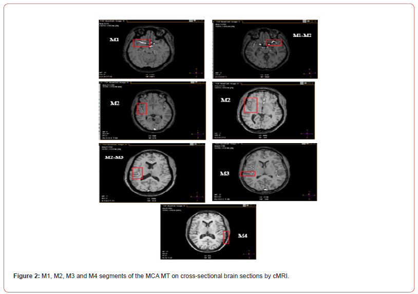
The Middle Cerebral Artery (MCA) represents a fundamental branch of cerebral vascularization [1-3]. During its course, the MCA will present four segments M1, M2, M3 and M4, [4-6] which constitute its main trunk (MT). The M1 or sphenoidal segment is basal and transverse. It extends from the termination of the Internal Cerebral Artery (ICA) to the limen insulae where it bifurcates. The M2 or insular segment is curvilinear and buried at the bottom of the lateral fossa of the brain (FLB) or Sylvian valley. It extends from the bifurcation of M1 to the posterosuperior angle of the insula, at the union of the upper and lower edges of the circular sulcus of the insula. Its distribution is variable [7] with 72% bifurcation, 12% trifurcation and 10% in multiple small trunks. From these trunks will depart the cortical collateral branches which reach the lateral face of the cerebral hemisphere (HC).
The M3 opercular segment corresponds to the portion located between the posterosuperior angle of the insula and the posterolateral end of the Lateral Sulcus (LS) or Sylvian sulcus. Thus, it is caught between the two lips of this LS which it crosses horizontally. The M4 cortical segment emerges from the posterolateral end of the LS and runs posteriorly along the surface of the cerebral convexity. The MCA terminates in the artery of the angular gyrus or artery of the curved fold, which arises at the posterolateral end of the LS and runs posteriorly and inferiorly towards the gyrus of the curved fold and the angular gyrus [8,9]. The collateral branches of the MCA are cortical (superficial) and central (deep). The MCA contracts superficial or leptomeningeal anastomoses with the Anterior Cerebral Artery (ACA) through its ascending collateral branches, and with the Posterior Cerebral Artery (PCA) through its descending collateral branches and its terminal branch.
These anastomoses are very important in ischemic stroke because they ensure the recovery of the MCA by the ACA or the PCA, thus reducing the infarction. On the other hand, the deep collateral branches do not present any anastomosis, hence the sensitivity to hypoxia of the territories they vascularize. The MCA presents anatomical variations. These are the duplication of the MCA (dMCA), the accessory MCA (aMCA) and the fenestration of the MCA [10]. Knowledge of these anatomical variations is important in the surgical dissection of cerebral aneurysms and in understanding collateral blood replacement in strokes associated with an MCA or an MCA. It is also of paramount importance during the morphological analysis of brain imaging. Thus, the objective of this work is to provide, by Magnetic Resonance Imaging (MRI), morphological data of the MCA to inform the interventions of neurovascular specialists in surgery and neuroimaging.
Table 1: Overview of metabolic and signal transduction pathways and their targeted therapy for RCC.

Methodology
Type of Study
Our study was longitudinal in nature with a descriptive and analytical aim. Anatomically, it was a fundamental study secondarily applied to imaging.
Subjects
We studied the morphology of the ACM in 40 cerebral hemispheres of 20 right-handed subjects.
These subjects met the following selection criteria:
Inclusion criteria:
a) Subjects aged between 18 and 55 years.
b) Subjects without macroscopic cranioencephalic lesions.
Non-inclusion criteria:
a) Subjects aged over 55 years.
b) Subjects under 18 years of age.
c) Recent or old macroscopic cranioencephalic lesions.
d) Subjects with a history of neurosurgical treatments.
Exclusion criteria
a) Subjects presenting early cortico-subcortical atrophy on brain
MRI.
b) Subjects presenting with brain lesions on brain MRI with or
without mass effect on the FLB.
These subjects were recruited consecutively following their registration for a scheduled brain MRI examination at the Diagnostic and Medical Imaging Center (CDIM) of the National University Hospital of Fann (CHNUF).
Materials
We used a Philips MRI from the Achieva range at 1.5 Tesla.
Image reconstruction, processing and exploitation were made possible
thanks to the integration of Philips DICOM Viewer R1.2 and
MILLENSYS Viewer 10.6 software in two of the console computers.
The standard image acquisition protocol was defined by the radiologist
[11,12]. These two sequences consisted of:
a) The T2-weighted spin echo (T2-SE) sequence with a RT equal
to 5950 ms and an ET equal to 110 ms. The flip angle was 90°
and the slices were frontal with a thickness of 5 mm.
b) The flight time (TOF) angiography gradient echo sequence,
with a RT equal to 23 ms and an ET equal to 6.9 ms. The flip
angle was 23° and the slices were transverse with a thickness
of 1.6 mm.
The frontal sections were strictly perpendicular to the white anterior commissure-posterior commissure (AC-PC) axis. The transverse sections were parallel to the AC-PC axis.
Methods Number of Trunks
At the level of each CH, we successively determined the number
of trunks existing at the origin of segment M1 and that of segment
M2.
a) The origin of M1 is located at the end of the ICA. On a frontal
T2-SE sequence passing through the M1 segment, it is clearly
identified at the medial end of the latter.
b) The origin of M2 is located just after the genu of the MCA, at its
exit from the falciform fold.
Synchronization of scanning of the three section planes (frontal, transverse and sagittal) was necessary to count the number of trunks without omitting one.
Modalities of the Trajectory of the Main Trunk (MT) of the MCA in the FLB
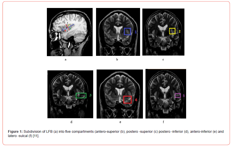
The behavior of the MCA MT has been described in the FLB. The FLB, in the study of Wade et al. was subdivided into five compartments using two planes, one parallel to the LS and a second perpendicular to it passing through the middle of the central insular sulcus (CIS) [11]. Four of the five compartments were located in the deep subarachnoid space of the FLB. These were the anterosuperior (1), posterosuperior (2), posteroinferior (3) and anteroinferior (4) compartments. Laterally, the entrance gate of the FLB that corresponded to the LS was considered the fifth lateral compartment (5) (Figure 1). The frontal sections passing at the level of the summit of the insula (SI) allowed the localization of the MT in the anterior compartments (1 and 4) of the FLB to be specified. Those passing at the level of the middle of the CIS specified the localization of the MT in the posterior compartments (2 and 3). The frontal section at the height of the posterosuperior angle of the insula allowed the localization of the MT in the lateral compartment (5).

Data Entry and Processing
After entry and extraction, the data were analyzed and then compared using Excel and Epi info software using the Student or Fischer test.
Ethical and Financial Considerations
Our study was approved by the Research Ethics Committee (REC) of Cheikh Anta Diop University in Dakar.
During our work, all data were collected in accordance with the rules of medical ethics. Subjects were informed about the procedures and objectives of the study. The protocols were designed and implemented in accordance with the recommandations of the Declaration of Helsinki.

Number of Trunks Visualized for Segments M1 and M2 of the MCA MT
a) At the right CH level : In 100% of cases, we found a single trunk
at the origin for the M1 segment of the MCA. The M2 segment
can present a single, double or triple trunk in 45%, 50% and
5% of cases respectively.
b) At the level of the left CH : In 100% of cases, we found a single
trunk at the origin for the M1 segment of the MCA. The M2 segment
can be single or double in 60% and 40% of cases respectively.
Modalities of the Trajectory of the MCA MT in the FLB
The behavior of the MCA MT has been described in the five
compartments of the FLB. The four compartments, anterosuperior
(1), anteroinferior (4), posterosuperior (2), and posteroinferior
(3), form the deep subarachnoid space of the FLB. The fifth compartment
corresponded to the lateral entrance of the FLB, i.e., the
LS. The secondary trunks and collateral branches of the MCA had a
particular distribution at the level of these five compartments.
a) At the right CH level : In front of the right FLB, the MT of the
MCA ran through the antero-inferior compartment (4) in
100% of cases. In its posterior trajectory, it ran through the
postero-inferior compartment (3) in 95% of cases. In the other
5% of cases, the MT was higher located along the medial edge
of the lateral compartment (5) located just above the postero-
inferior compartment. The posterior end of the lateral compartment
(5) opposite the postero-superior recess (PSR) of
the FLB was crossed in 100% of cases by the M3 segment of
the MT. In no case did the MT cross the antero-superior (1) and
postero-superior (2) compartments. However, these last two
compartments could be occupied either by a secondary trunk
or by collateral branches of the MCA.
b) At the level of the left CH : For the left FLB, the MT occupied both
the antero-inferior (4) and postero-inferior (3) compartments
in 100% of cases, at the bottom of the posterior marginal sulcus
of the insula (part of the circular sulcus of the insula). The
antero-superior (1) and postero-superior (2) compartments
were occupied by a secondary trunk or ascending collateral
branches. The lateral compartment (5) was always crossed in
front by the collateral branches of M2 which could be accompanied
by a secondary trunk. At its posterior end, at the height
of the postero-superior angle of the insula, the M3 segment of
the MT was present in 100% of HCs. Moreover, at this level, the
junction between M2 and M3 appeared as an elbow or loop
sinking into the PSR of the FLB.
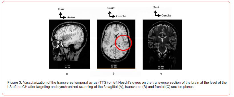
Generally speaking, and regardless of the CH concerned, the MT ran along the bottom of the inferior partition (compartments 3 and 4) of the FLB, that is to say along the posterior marginal sulcus. At the end of this, which corresponded to the PSR of the FLB, it bent and crossed the LS. Inside the LS, it crossed the transverse temporal gyrus (TTG) or Heschl’s gyrus before emerging on the superficial and lateral cortical surface of the CH (Figure 3). Furthermore, for both hemispheres, the ascending collateral branches, when visualized, had an identical trajectory at the level of the anterosuperior (1) and posterosuperior (2) compartments. They joined the insular cortical wall, ran upwards to the level of the superior marginal sulcus.

At this level, each ascending collateral branch bent downwards and then descended along the superolateral opercular wall of the FLB before penetrating the SL from its medial edge. This trajectory gave it a «loop» appearance, the width of which was greater in front at the level of the apex of the insula and clearly visible on transverse sections. Behind, the narrowness of the FLB barely allowed the «loop» appearance of these ascending collateral branches to be seen. The descending collateral branches were visible at the level of the LS, which they crossed almost horizontally. The secondary trunks of the MCA arising after the M1 segment had a very variable trajectory. They could be found at the level of all compartments but more frequently along the upper part of the antero-inferior (4) and postero-inferior (3) compartments.
Discussion
Main Trunk (MT) Segmentation
The MCA is the largest and most complex of the cerebral vessels due to its anatomical variability [4,5]. Like all cerebral arteries, it has two portions : a basal portion (M1) and a cortical portion (M2, M3 and M4). From the M1 segment, central or basal collateral branches depart. At the level of M2, ascending and descending cortical collateral branches depart. The M2 segment is successively followed by segments 3 and 4. The cMRI images from our study offer the same segmental description with a MT made up of segments, as in classical anatomy books [1-3]. Moreover, according to the study by Wade et al. Regarding the morphometry of the MCA, the luminal diameter comparison tests of the four segments showed a progressive decrease confirming the idea that the 4 segments continue the same axis from the ICA but gradually decrease in diameter until the last segment M4 [12]. However, for other authors, the cortical branches that run along the insular cortical surface to the upper edge of the circular sulcus of the insula correspond to M2 segments [5] and therefore to multiple trunks.
Number of Trunks Visualized for Segments M1 and M2
a) Segment M1 Our results show that M1 presents a single trunk for all CH. A larger number of M1 trunks may be associated with vascular anomalies such as MCA duplication (dMCA) or accessory MCA (aMCA). Komiyama et al. found in their study on 500 angiograms, a prevalence of 0.4% for each anomaly. He cite other frequencies in the order of 0.2 to 2.9% for dMCA. For aMCA, the cited frequencies ranged from 0.3 to 4.0% [10]. In his own work, however, he establishes the link that all cases of anomalies were associated with a vascular le sion such as aneurysm, stenosis and vascular occlusion. However, more recent work shows that the dACM and the aACM are rare anatomical variations, not systematically associated with pathologies [13]. In addition, it is specified that the ACM is a hypertrophied collateral of the ACA, which results from the fusion of several collaterals, explaining the existence sometimes of more than one M1 segment in the event of non-fusion. The subjects of our study were free from all cerebral vascular pathologies and anomalies. This could explain the presence of a single trunk of M1.
b) Segment M2 Concerning the M2 segment, the separation into two or three trunks is often described in the literature but with variable proportions. Our results are similar to studies [1-3] found in the literature where the presentation in a single trunk remains modal except that in these studies, the CHs were not studied separately. Regarding the present study, the variations are presented differently according to the CH because the single trunk of M2 is more frequent at the level of the left CH. On the right, it is the bifurcation into two trunks which predominates but only by more than 5%. Harada and Gibo found frequencies of 72% and 78% respectively for the bifurcation into two trunks of M2 [5,14]. The single trunk for the M2 was not described by these two authors but with good observation, the schematic illustrations they provided for the multiple trunks of M2 correspond to the existence of a trunk and its collaterals. Indeed, the illustration diagram shows a MT formed of the four segments, associated with small secondary trunks detaching from M2 before branching out.
MCA MT Trajectory
To study the trajectory of the MCA MT, we subdivided the FLB using two lines, one parallel to the LS on the lateral face of the CH and a second perpendicular to it passing through the middle of the CIS. This resulted in five compartments, four of which were located in the deep Subarachnoid space (SAS) of the FLB. These are the anterosuperior (1), anteroinferior (4), posterosuperior (2), and posteroinferior (3) compartments. The fifth compartment corresponds to the ls (5) along its entire length. This subdivision made it possible to easily trace the modal trajectory of the MCA MT. MRI images, three levels of frontal slices allowed a better exposure of these compartments. These are the frontal slices passing through the IS, the middle of the CIS and the level of the posterosuperior angle of the insula. The anterior frontal slice at the level of the IS shows us the anterior-superior compartment which is annotated 1 and the compartment anterior-inferior annotated 4.
The second frontal section in the middle of the CIS shows us the posterosuperior compartment which is annotated 2 and the posteroinferior compartment annotated 3. The third frontal section at the posterosuperior angle of the insula shows the LS compartment annotated 5. Furthermore, these frontal section levels clearly expose the different luminal diameters of each of the four segments of the MCA thus allowing, after comparative measurement, to differentiate the MT from the secondary trunks of the MCA. Indeed, when the MCA has more than one trunk, it is the one with the largest luminal diameter that is considered its MT. When the trunks are of equal diameter, it is the one that takes the classic trajectory to the bottom of the LS to end with the angular artery, which is considered the MT. Thus, a MT was identified at the level of each CH. Our results show a trajectory of the MT of the MCA which is described as horizontal for M1, sinuous for M2 which is directed backward and upward, almost horizontal for M3 and slightly sinuous for M4.
In addition, this trajectory is determined according to the five compartments defined previously. This provides a better systematization and precision in its understanding and exploitation. The antero-inferior (4) and postero-inferior (3) compartments constitute the privileged inferior corridor of the MT. In this inferior corridor filled by the deep SAS, it runs backward along the posterior edge of the circular sulcus of the insula. In the posterior part of the postero-inferior compartment (3), it heads upwards, getting closer and closer to the medial edge of the LS. From the posterosuperior angle of the insula, it follows the bottom of the LS before emerging at the lateral cortical surface where it ends in the angular artery or ulnar artery. Gibo et al. Described a modal distribution of M2 when there is more than one trunk. They conclude that the lower trunk is dominant with a frequency of the order of 38% higher than that of the other trunks [5]. In the illustrations of their study we note that this dominant lower trunk runs along the lower corridor, which is consistent with our results.
In Summary
The M2 segment of the MCA poses a substantial obstacle to any open or stereotaxic procedure targeting the FLB and its surrounding structures such as the insula. In the case of MCA aneurysm surgery, the direction of the vascular segments is an important factor for MCA exposure. Moreover, the surgical difficulties encountered during its treatment are due in part to the complex variability of MCA anatomy. Furthermore, advance knowledge of MCA variations is also necessary for surgery of large lesions requiring significant exposure. It is also necessary for targeted opening. Mastering one’s anatomical knowledge of the MCA will allow one to develop an appropriate surgical plan to minimize upfront manipulation of the vessels and brain, avoid unnecessary intraoperative navigation, and choose the safest and most direct method to approach the MCA. In some cases, it may be difficult to plan the operation when an intracerebral hemorrhage or a lesion mass alters the radiographic presentation of the MCA. The symmetry found in the trajectory of the MT of the MCA could offer the surgeon the opportunity to conclude through the MCA opposite to the affected one.
Conclusion
Objective indicators on MCA are necessary especially for proper interpretation in neuroimaging and also for neurosurgeon trainees so that they can make appropriate surgical decisions. Morphological results obtained on MCA can contribute to the development of these indicators.
- Dubret G, Cousin FR (1985) Elements of Anatomy and Physiology of the Central Nervous System. Flammarion PP.
- Rouvière H, Delmas A (2002) Central nervous system, pathways and nerve centers. In: Human anatomy. Descriptive topographical and functional. Masson PP. 411.
- Vitte E, Chevallier JM (1998) Neuro-Anatomy. Flammarion PP.
- Elsharkawy A, Niemelä M, Lehecka M, Lehto H, Jahromi BR, et al. (2013) Focused opening of the sylvian fissure for microsurgical management of MCA aneurysms. Acta Neurosurg 156(1): 17‑25.
- Gibo H, Carver CC, Rhoton AL, Lenkey C, Mitchell RJ, et al. (1981) Microsurgical anatomy of the middle cerebral artery. J Neurosurg 54(2): 151‑169.
- Hacking C, Jones J (2017) Middle cerebral artery.
- Maslehaty H, Cornelius D, Kleist B, Goricke S, Sure C, et al. (2017) Computed Tomography- and Magnetic Resonance Image-based Analysis of the Anatomical Variations of the Sylvian Fissure and Characteristics of the Middle Cerebral Artery. Clin Pract 7(1): 890.
- FitzGerald MJ, Folan-Curran J (2003) Clinical neuroanatomy and related neuroscience. Maloine PP. 323.
- Kamina P (2013) Neuroanatomy. Maloine PP.
- Komiyama M, Nakajima H, Nishikawa M, Yasui T (1998) Middle Cerebral Artery Variations: Duplicated and Accessory Arteries. J Neuroradiol 19(1): 45-49.
- Wade R, Plaisant O, Guédon A, Diop AD, Ndiaye A, et al. (2019) Morphology of the lateral fossa of the brain (sylvian valley): anatomo-radiological aspects and surgical application. Surg Radiol Anat 41(6): 639-655.
- Wade-Kane R, Seye C, Gaye M, Ndiaye A, Mar NB, et al. (2022) Morphometry of the middle cerebral artery (sylvian artery) on MRI: Contribution to cerebral endovascular surgery. Journal of Neurology, Neurological Science and Disorders 8(1): 001-006.
- org (2018) Middle cerebral artery.
- Harada N, Kondo K, Miyazaki C, Nomoto J, Kitajima S (2011) Modified three-dimensional brain model for study of the trans-Sylvian approach. Neurol Med Chir 51(8): 567-5
-
Racky WADE*, Mamadou NDIAYE, Magaye GAYE, Aïnina NDIAYE, Ndeye Bigué MAR, Sokhna BA, Jean Marc NDOYE, Mamadou DIOP, and Abdoulaye NDIAYE. Morphology of The Middle Cerebral Artery (Sylvian Artery) on MRI: Interest in Surgery and Imaging. Anat & Physiol Open Access J. 2(1): 2025. APOAJ.MS.ID.000526.
-
Middle cerebral artery; morphology surgery imaging (MRI); iris publishers; iris publisher’s group
-

This work is licensed under a Creative Commons Attribution-NonCommercial 4.0 International License.


