 Review Article
Design and Performance of Capacitive Coupled Conductivity Sensor for Marine Applications
Srinivasan R1*, Saikumar V2, Boby George2, Tata Sudhakar1 and Ramadass GA1
1National Institute of Ocean Technology, ESSO, Ministry of Earth Sciences, India
2Indian Institute of Technology, Madras, India
Srinivasan R, National Institute of Ocean Technology, ESSO, Ministry of Earth Sciences, Chennai – 600100, India.
Received Date: September 29, 2021; Published Date: October 18, 2021
Abstract
Conductivity is the intrinsic property of sea water from which the salinity can be determined, and the measurement of salinity is a regulatory requirement. This work is aimed at developing a conductivity sensor for Ocean Observation applications. The concept of capacitive coupling is attempted in combination with contact electrodes while designing the conductivity probe which eliminates the polarization and lead, or electrode contamination issues associated with regular electrode type conductivity measurement methods. This approach also confines fixed the cell constant and hence the defined current path in the probe. In this method, the probe design combines the advantages of contact type and capacitively coupled method. The probe has three circular contact type electrodes (exciting electrode, receiving electrode and dummy electrode) and two circular capacitively coupled voltage electrodes (dielectric coating over the metal electrodes). The contact type electrodes act as the current electrodes similar to the four-electrode method; Contactless electrodes act as the potential electrodes. When the exciting electrode is excited, the current will start flowing into the water and collected by the receiver electrode. If used for conductivity measurement of sea water the entire probe will be surrounded by sea water and insulator over the electrode will avoid direct contact of electrode with surrounding water. In such an application, dummy electrode will make sure that no current flows in the surrounding water and ensures that the path of current includes only the water inside the pipe between the excitation and receiver electrodes. The insulated voltage electrodes are metal electrodes coated with a dielectric material. Thus, a capacitance is formed between the metal electrodes and the outer surface of water in the tube. Suitable sensitive electronic circuitry is developed to measure the resistance of the water column in-turn the conductivity of liquid is measured.
Keywords: Conductivity, Ocean observation, Contact electrodes, Capacitive coupling, Dielectric material.
Introduction
Five Electrode Method
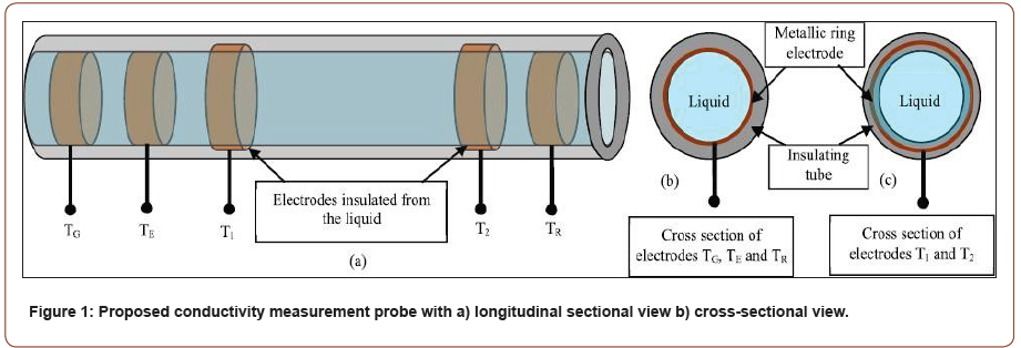
There exist various methods to measure the conductivity of a liquid such as electrode methods and non-contact methods including inductive types. In this developmental work a combination of contact electrodes and capacitively coupled noncontact electrodes are effectively used to avail the advantages of the above indicated methods. The probe has three circular contact type electrodes (exciting electrode TE, receiving electrode TR and dummy electrode TG) and two circular capacitively coupled voltage electrodes T1, T2(dielectric coating over the metal electrodes). The contact type electrodes act as the current electrodes similar to the four electrode method; T1 and T2 act as the potential electrodes. When the exciting electrode is excited, the current will start flowing into the water and collected by the receiver electrode. If used for conductivity measurement of sea water the entire probe will be surrounded by sea water and insulator over the electrode will avoid direct contact of electrode with surrounding water. In such an application, dummy electrode will make sure that no current flows in the surrounding water and ensures that the path of current includes only the water inside the pipe between the excitation and receiver electrodes. Figure 1 shows the new probe that is incorporated with five electrodes. Three electrodes are contact electrodes and they are not sensitive to final output. The two sensitive electrodes are insulated from water.
The insulated voltage electrodes, T1 and T2 are metal electrodes coated with a dielectric material. Thus, a capacitance Cx1 is formed between the T1 metal electrode and the outer surface of water in the tube; similarly, Cx2 is formed between T2 metal electrode and outer surface of water in the tube. A prototype of the probe (refer Figure 2) measurement circuit has been built and tested.


Results
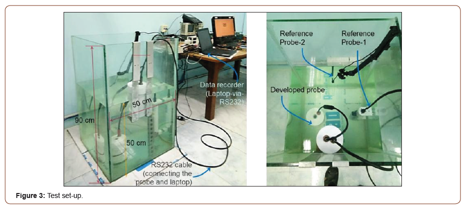
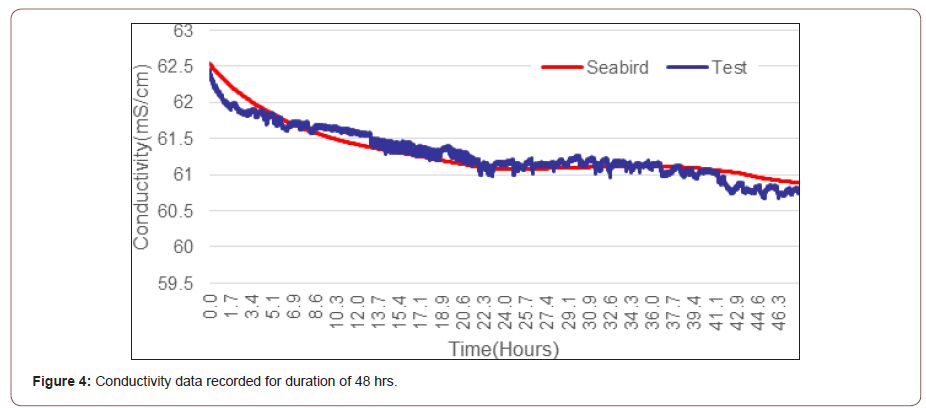
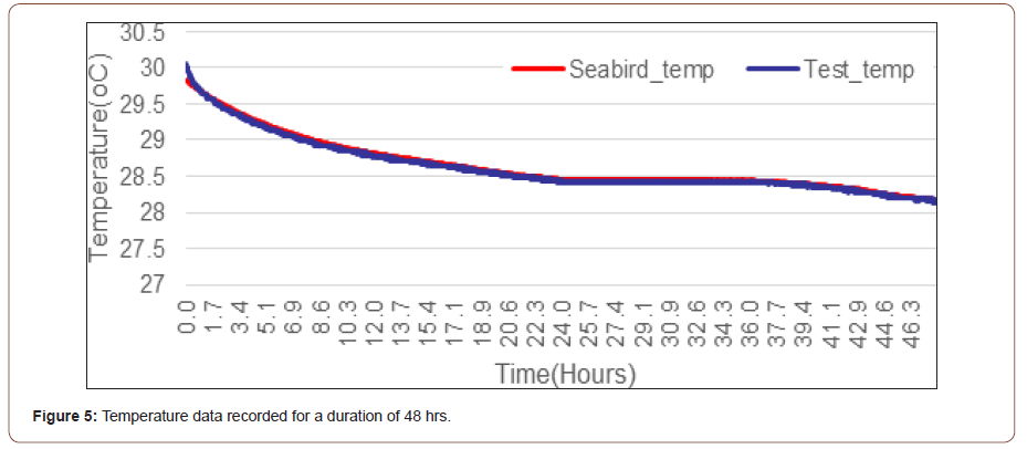
The proto unit tested in a glass tank having a height of 90 cm, width of 50 cm (rectangular). The tank was filled with seawater for 50 cm height with a volume of 125 Litre. A pictorial view of the test set-up is shown in Figure 3. The indigenized probe unit and the Seabird reference CTD sensor was dipped in to the water for a week period and samples were recorded. The output of the probe was recorded (temperature, pressure, and conductivity) in a laptop which was connected to the probe via an underwater rated signal - RS232 cable. Some of the results are presented in Figure 4 & 5, displaying the conductivity and temperature data, and the deviation in the measurement. In this process, the output of the indigenized CTD probe and the Seabird - reference CTD sensor is directly compared and data plots were made.


Discussion & Conclusion
In this article, we have described the performance and comparison of indigenously developed proto units of capacitively coupled conductivity sensor and the imported SeaBird CTD sensor at controlled laboratory environment conditions. Additionally, the results presented above, for 48 hrs, show that the maximum deviation seen in the conductivity is ± 0.3 mS/cm and similarly for the temperature measurements the error is less than ± 0.25 oC. This temperature deviation is noted in the beginning. It could be because the water column has taken some time to settle to the same temperature across the cross- section. The locations of the indigenized sensor and the reference CTD sensor are slightly different. After the initial deviation, the maximum deviation seen in temperature reading is less than ± 0.1 oC. Future work is to integrate all the sensors in a single enclosure and to design a slicker version of PCB with electrodes. Also extending the operational range of proto unit to 500 m depth is one of prime objective.
Acknowledgement
We are thankful to the Ministry of Earth Sciences, Govt. of India for funded and entrusted this development works to National Institute of Ocean Technology, Chennai.
Conflict of Interest
None.
-
Srinivasan R*, Saikumar V, Boby George, Tata Sudhakar, Ramadass GA. Design and Performance of Capacitive Coupled Conductivity Sensor for Marine Applications. Ad Oceanogr & Marine Biol. 3(1): 2021. AOMB.MS.ID.000552.
-
Conductivity, Ocean observation, Contact electrodes, Capacitive coupling, Dielectric material
-

This work is licensed under a Creative Commons Attribution-NonCommercial 4.0 International License.


