

 Research Article
CO2 Reactivity with Potassium and Strength of Densified Charcoal
Received Date:January 18, 2024; Published Date:January 26, 2024
Introduction and Background
There is an ongoing urge to reduce the CO2 emissions from the Mn-ferroalloy industry. The GWP (Global Warming Potential) is reported to be between 5 and 7 kg/kg Mn1 in countries like Australia, China, France, India, South Africa, and the USA. This numbers will hence be lower in countries with a high amount of hydropower like e.g. Norway. From “cradle to gate” the two largest contributions to the GWP are the energy to the smelters and the carbon used as reductants. To reduce the CO2 emissions from the use of reductant in the metal producing industry, the use of charred biomass is one of the mitigations that may be used [1-3]. So far, charcoal is the most matured charred biomass that is developed to be used as a reductant.
In the Mn-ferroalloy submerged arc furnace process, manganese oxide ores are mixed with carbon materials and heated to 1400- 1600°C. In the high temperature zone, the carbon is used to remove the oxygen from the manganese oxide according to reaction [1]. MnO will be in a liquid slag, consisting of SiO2, Al2O3, CaO and MgO, and Mn in the liquid metal phase with Fe and dissolved C.

The CO gas will rise to the colder zones of the furnace and reduce the higher manganese oxides according to reactions [2], [3] and [4].
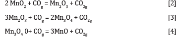
The CO2 produced from these reactions will react with the carbon materials, according to the Boudouard reaction, reaction [5]. The Boudoard reaction is endothermic and will hence increase the energy consumption. Additionally, all carbon material added to the furnace, with the exemption of the dissolved carbon in the metal, will end up as CO2 emissions, and hence a larger consumption of solid carbon will increase the total CO2 emissions and hence the GWP. It may exit the furnace as CO gas and be combusted to CO2 at the plant or be oxidized in a subsequent process, however it will finally be oxidized to CO2 either way. The occurrence of the Boudouard reaction will hence increase the CO2 emissions from the process.

The gas produced in the process must be evenly distributed in the charge to have a good prereduction according to reaction [2]-[4]. The gas produced must be able to exit the furnace, to avoid pressure built-up, and hence lumpy raw materials are used. Fine materials may plug the gas flow. Fine carbon materials may also leave the furnace with the gas, and hence fine materials must be avoided. The materials added to the furnace will hence require a good mechanical strength, to avoid fines formation during handling and heating in the furnace. The carbon materials used in the Mn-ferroalloy have a number of requirements [4-6]. The chemical composition, as Fix C and extent of trace elements, will always be significant. As the heat is produced through the resistive heating of the coke bed, the electrical resistivity of the carbon materials must be evaluated. Slag reactivity according to reaction [1] have also been investigated [7]. When transferring from metallurgical coke to charcoal, it is seen that the CO2 reactivity is higher and the mechanical strength is lower for charcoal [4-6], and hence this paper will mainly focus on the CO2 reactivity according to the Boudouard reaction (reaction [5]) as well as the mechanical strength.
The common way to describe the CO2 reactivity is as described originally by Ergun (1956) [8] shown in reaction [6] and [7] CO2 molecules will react with free carbon sites (Cf) producing a CO molecule and leave an oxygen atom adsorbed at the carbon site (CO). This is a reversable reaction and has a forward and backward rate given by the rate constant k1 and k’1 respectively. The attached oxygen atom will react with the solid carbon to CO and again free the C-surface producing from 0, 1 or 2 free carbon sites (n), but will most likely be 1.
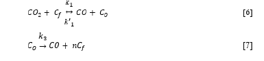
The overall rate expression was originally given by Ergun (1956) [8], but is still being improved by e.g. Mianowski et al. (2016) [9]. The rate of gasification is determined by type of carbon material (mineral matter, volatile content, mesopore volume, specific surface area, crystalline structures [10] as well as particle size, gas pressure and temperature. Kwon et al. [1988] [11] found that the reaction rate of char from coals in N2-CO2 mixtures was proportional to the CO2 pressure and had an activation energy between 80-150 kJ/mol, while Huo et al (2014) [10] measured activation energies between 130 and 180 kJ/mol for chars from biomass, coals and petroleum coke, and Hovd (2017) [12] about 200kJ/mol for both charcoal and metallurgical coke. In 50%CO2-50%CO Kaffash and Tangstad found an activation energy of 60 and 150 kJ/mol for charcoal and coke respectively, and found little change when the materials were impregnated with potassium [13]. The extent of gasification in the Mn-ferroalloy furnaces is around 20% combustion of the carbon materials with CO2 gas according to reaction [5] [14]. From 0 to 20% gasification the amount of carbon gasified are quite linear with time and can hence be simplified. The rate (%Fix C/s) is thus constant for a given carbon material, at given gas flow and given temperature [2,15].
Mn-ores contain small amounts of alkalis, and typically less than 2% of the main alkali K2O4. When the ore reach the high temperature area the potassium oxide will be reduced to K(g), which will follow the gas into the low temperature zones, and then oxidize to K2CO3 or K2O. The potassium compound will then follow the raw materials down in the high temperature zone again. This means that it will be an accumulation of potassium in the furnace, many times higher than what is coming from the raw materials. Based on mass balances of in and out flows, it has been calculated to be tons of potassium accumulated [16]. In an industrial excavation of a Mnferroalloy furnace in 2021, it was seen that the carbon materials in the coke bed contained 3.5% K2O. In the lower temperature zone, one must assume that the potassium content deposited is much higher. Water was used to cool the furnace under the excavation, and as the potassium species dissolve in water, one can assume that the deposited amount of K2O on the carbon materials in the low temperature zone under operation was much higher than 3.5% K2O.
The presence of alkalis has a catalytic influence on the Boudouard reactivity [13,15,17–19]. The mechanism was advocated by Rao et al (1982) [17] to go through a cyclic mechanism K2CO3→K(g)→K2CO3, and the rate would depend on the state of the carbonate. Above the melting points, that is above 900 °C, the catalytic ranking of the alkali carbonates would be K2CO3>Na2CO3>Li2CO3. Alam (1984) [15] also found that the rate was linear with CO2 pressure, was decreasing with CO pressure, and 3% Na2CO3 was found to increase the reaction rate by a factor of 10 for two cokes. The effect of alkalis was much larger than the difference in the low-reactivity and highreactivity coke. Liu et al. 2018 [19] saw that different forms of Nacompounds would give different combustion rates of coals when adding NaCl, Na2SO4 and NaOH. Kirtania et al. 2017 [18], verified that NaC was slower than Na- and K-carbonates.
The strength of the carbon can be measured by tumbling tests (abrasive tests), by single particle compression tests and by bulk compression test [20,21]. Saito et al. (2022) [20] investigated cokes and found that the compression strength at high temperatures was higher than at room temperature. It is however assumed that the room temperature measurements are showing the same trend as the high temperature measurements and hence, most measurements are done at room temperature. For cokes it was seen that the pores larger than 1000μm was lowering the strength20. For charcoals, generally the density is correlated to increasing strength, and a slow pyrolysis will increase the decomposition of carbon from the volatiles and hence increase the density as well as the strength [2,22,23].
To reduce the CO2 emissions, that is the GWP in the Mn-ferroalloy industry, one suggestion is to use charcoal instead of fossil fuels like metallurgical coke. As the porosity is high and density is low in charcoal, the CO2 reactivity is high, and the mechanical strength is low. One way to mitigate these effects is to densify charcoal by decomposing methane at the charcoal, adding solid carbon in, and at, the charcoal, and additionally produce H2 gas according to reaction [6]. To determine how the CO2 reactivity will be inside the Mn-ferroalloy furnace, the catalytic effect of K must be included. Kaffash simulated the Mn-furnace by using gas impregnation to add K to the samples [13,24]. As this is a very resource demanding experimental technique, the goal of this study is to determine if wet impregnation can replace the gas-impregnation. The second goal of the study, will be to determine the CO2 reactivity of potassium impregnated charcoal and the last goal is to determine the strength of densified charcoal.

Materials and Methods
Feedstock Materials
Industrial charcoal was used for densification experiments, CO2 reactivity and mechanical strength measurements. A metallurgical coke (Met.coke) was used as reference material for CO2 reactivity. The materials were crushed, splitted and sieved to 6.68–15.00 mm. To reduce the variance in the density experiments, the size range of 10-13mm was later used. The proximate analysis and K2O content of the materials are shown in Table 1.
Table 1:The proximate analysis performed by Sintef Norlab. K2O is given as a percentage of the total amount of ash. (CharcoalHT is charcoal heated to 1100°C in Ar).

Densification
The densification was done in an induction ENTECH 1450 furnace. The heating is controlled by a temperature controller (Eurotherm 2408). The wall temperature, crucible temperature and effect is logged. The purging gas is fed by mass flow controls from Alicat Scientific. An induction ENTECH 1450 furnace was used to heat up the charcoal in a high carbon steel crucible. The gas is heated in the dual-walled crucible before it goes through the charcoal. The S type thermocouple (platinum rhodium—10% Pt) is protected by a ceramic tube. The thermocouple is centered in the charcoal sample.
A total of 350 g (about 12cm height) of charcoal was used. The charcoal was heated to the predetermined temperature, in an Ar flow of 3 L/min at standard temperature and pressure (STP) in a heating rate of 20 K/min to 500°C and 10 K/min to 1100°C. Some experiments were only heated with Ar and then stopped. This to compare the heated material, to the material that was densified with methane. For the Ar experiments, the furnace was turned off at the predetermined temperature, and the crucible with charcoal was left in the furnace to cool, with purging gas. The gas was stopped when the temperature was below 200°C and the charcoal was left to cool in the furnace overnight. After the experiment the weight was recorded. For the methane experiments, after the initial heating step with argon as purging gas, argon is substituted with methane, having a flow rate of 3 L/min (STP). After the predetermined time, the furnace was turned off. During cooling it was purged with argon gas (3 L/min (STP)) until the temperature was below 20°C. After the experiment the sample was weighed to record weight loss. The difference between mass reduction of materials under Ar and the mass reduction under Ar followed by methane would determine the carbon deposition percentage. The methane yield was calculated based on how much carbon was deposited of the total carbon in the methane gas.
Potassium Impregnation
To simulate the Mn-ferroalloy furnace conditions with deposited alkalis on the carbon particles, the impregnation of samples by potassium compounds is required. Two methods were used; gas impregnation, to simulate the Mn-ferroalloy furnace, and the simpler wet impregnation method. The gas impregnation method was developed for testing aluminium carbon electrodes [25]. By heating 75g potassium carbonate (K2CO3) and 15g active carbon powder in a steel crucible, potassium gas is formed. 200g charcoal or metallurgical coke was placed in a basket on top of the potassium-gas forming crucible. The crucible was kept at 1000°C for the time it would take to reach the designated potassium content. After cooling, the charcoal, or coke, was divided in three layers, where the two bottom layers contained a higher K-content than the top layer. Each layer was analyzed for potassium at SINTEF Norlab.
The wet K-impregnation of charcoal is performed in a beaker with a solution of distilled water and potassium carbonate (K2CO3). A magnetic stirrer is used for the whole experiment with a stirring rate of 700 rpm at 80°C. When the solution is at 80°C the charcoal is added to the solution and then stirred for 60 minutes. After the charcoal has stayed in the solution for 60 minutes, the solution is poured out of the beaker and the charcoal is dried at 100°C for 24h in a muffle furnace in an oxidizing atmosphere (air). It is performed experiments with 1, 2.5 and 5 M.
CO2 Reactivity Test
A macro-TGA (thermogravimetric analyses) furnace, using a Mettler Toledo PB 1502 balance (with an accuracy of 0.1 g), was used to measure the CO2 reactivity. 50% CO2 and 50% CO (4 Nl/ min) was used to simulate the conditions inside the Mn-ferroalloy furnace. The sample was heated in Ar gas to 1070°C. 30–40 g of carbon material was placed at the bottom of the stainless-steel crucible on a ceramic perforated plate. The gas was heated in the dual-walled crucible before it was purged through the ceramic perforated plate and then the carbon material. When 20% of the fixed carbon was gasified, the experiment was ended. This is typically the amount of carbon that is combusted by the Boudouard reaction in ferromanganese production. The experiment was ended by withdrawing the sample from the hot zone and purging with inert gas. This method is previously described in [13,24,26]. The furnace temperature is controlled by a thermocouple connected to a Eurotherm 2408 controller. Based on the weight versus time curve, the CO2 reactivity given in %FixC/time is found.
Characterization Methods
The volatile matter and the ash content of charcoal and coke was measured according to DIN 51720, DIN EN 14775 and DIN 51719 respectively. Fixed carbon content was calculated from the ash and volatile content: fixed carbon = 100% - ash content - volatile matter content. SEM/ EDS analysis on a high-resolution microscope ULTRA 55 (Zeiss, Germany) under high vacuum was used on the impregnated and non-impregnated samples to see the structural properties of the samples. ImageJ was used to calculate the porosity based on visual pores.
The particle density (bulk density) was measured by manually measuring the mass and volume of specimen-cubes, by the use of a mm-scaled ruler and a weight (to the nearest 0,001 g). The absolute, skeletal density, or sometimes called true density, was measured by the use of gas-pycnometry in an Accupyc II 1340, which is a two-chamber gas displacement pycnometry system using He. The machine normally runs with 5-10 iterations per sample, to get as low uncertainty as possible. Porosity can be defined as the ratio between the pore volume (Vp) and the total bulkvolume. Computational Tomography (CT) was used to evaluate the distribution of the potassium present in the charcoal particles. The compression-test was performed with a Zwick/Roell Z2.5 material testing machine. The samples were placed in a small bowl, and exposed to compression-forces by a 1, 7·1, 7 cm2 area crosshead, which runs at a speed of about 2 mm/min. In order to measure the charcoals abrasive properties as a function of densification, the different samples were exposed to a drumming process with the Hanover drum. Each drumming-process lasted for 30 minutes, and the speed was adjusted to 40 rounds per minute. The inside of the drum has a diameter of 21 cm, a depth of 10 cm, and four wings. Each drumming process was followed up by a 15-minutelong sieving-process.
Results and Discussions
The results and discussion part will be divided into the densification of charcoal and the CO2 reactivity of the carbon materials. The densification process will have a cost when it comes to the energy consumption that must be evaluated based on the quality of the products, that is the off-gas containing CH4 and H2, and the solid carbon produced. The CO2 reactivity is of importance when the carbon materials will be used in metallurgical processes. Here the reactivity of charcoal and densified charcoal will be compared to the metallurgical coke that is mainly used in the industry today. As most metallurgical processes have circulation of potassium, this must be taken into account. Finally, the mechanical strength will be shortly discussed, as the production of fines in industrial furnaces may cause instability in the furnace.
The amount of deposited carbon on the charcoal is seen in Figure 1. As expected, the amount increases with increasing time. The maximum amount of carbon deposited is seen to be linear with time, until at 3 hours where it is slightly lower. The uncertainty is however quite high in the amount deposited and hence the 3 hour point may be on the linear trend. It shows that even after 30% deposition that we are not close to saturate the charcoal, and with longer time one could probably continue to deposit even higher amounts. This may be due to the high porosity, which has been measured to be 62-75% which is in agreement with previous measurements [24] One can also see in the figure that the uncertainty is very high, and at 3 hours purging time the percent deposited carbon varies between 17-30%. In the earlier experiment a larger size distribution of 7-15mm was used. It was later narrowed to 10-13mm to get more homogeneous gas flow through the charcoal. With gas channeling in the bed, the amount of deposited carbon will vary significantly, and in a future process, the gas flow through the charcoal must be controlled.

In the experimental apparatus the temperature varied in some of the experiments, however as seen in Figure 1, the average temperature is not showing any correlation with the amount of deposited carbon. Figure 2 shows the methane yield in the experiments. For the 10-13mm charcoal experiments the methane yield, or amount of carbon in the methane depositing on the charcoal was between 40 and 50%. For the experiments using 7-15mm, the yield was lower, even down to a couple of percentages. This verifies that the gas has been channeling in the charge and the methane has not had time to crack and deposit the carbon on the charcoal. In some preliminary experiments where methane gas flow was checked out, it was shown that a higher gas flow was not increasing the deposition of carbon, which also indicates that the gas needs some time in the charcoal to crack and deposit.


Based on the experiments so far a mass and energy balance has been done per ton of Fix C in the charcoal (Figure 3). The balance is done on the assumption of 30% carbon deposition and a methane yield of 50%, and hence 1375kg of Fix C will be produced per ton Fix C in. The raw materials will enter the process at 25°C and the process will run at 1100°C. As the cracking (reaction [6]) is an endothermic reaction, the process will require 2700 kWh electric energy, and produce a gas containing mainly methane and hydrogen gas in a H2/(CH4+volatiles) volume ratio of 1.4, or put in in another way: 58%H2 in the off gas. At 1100°C all of the CH4 should crack to solid carbon and H2 according to the equilibrium partial pressures of CH4 and H2 shown in Figure 4. If the off gas containing 58% H2 was to be recycled to the process, the driving force of the cracking reaction would decrease by at least 58% as the partial pressure of CH4 decreases from 1 to 42% comparing the first and second run of the gas. The driving force is here assumed to be proportional to the CH4 pressure, but is actually equal to the distance from equilibrium, and hence the rate could be even lower at the second run. The major part of the energy in and out will be in the chemical energy in the solid carbon and CH4/H2 in and out. The thermal energy in the carbon and the off gas will be 2068 kWh.
Both the wet- and dry-impregnation of K charcoal particles was investigated in CT and SEM. As the charcoal particles vary quite a lot in structure, and also that each charcoal particle would see different amount of K-gas in the gas impregnation, it was not possible to say if the two types of impregnation would give large differences, as only a few particles was studied in SEM and CT and shown in Figures 5 and 6. There was an indication that the wet impregnation was more distributed among all particles, while in the gas impregnation some particles had large amount of K both on the surface, but also distributed throughout while some particles did not have any K on the surface or inside the particles. In Figure 5 one can see K-layers inside the pores during gas impregnation, and in Figure 6, the potassium is as single crystals on the surface. In the previous work [27] it was indicated that the wet-impregnated K-particles was generally larger in size than the gas impregnated particles, however this was not seen here as shown in Figure 6. To sum it up, the potassium gas impregnation would sometimes give a dense layer in the charcoal particle, where both gas impregnation and wet impregnation would give single crystals, or clusters of crystals. This must however be further investigated. K was found in the centre of charcoal particles for both impregnation methods, and the crystals seem to be in the μm area.
As seen in previous publication [13,15,17-19], the CO2 reactivity increases with amount of K present, as seen in Figure 7. Without any impregnation of potassium, there is a large difference between the CO2 reactivity for different carbon materials, where the charcoal has one order of magnitude higher CO2 reactivity compared to the metallurgical coke. Densified charcoal will be somewhere between them. It is however seen that when the charcoal is impregnated with potassium, the CO2 reactivity ends up in the same area. Based on industrial excavation of a Mn-ferroalloy furnace, it is evaluated that the K-content on the carbon materials are higher than 3.5%K in the area where the Boudouard reaction is active. The figure shows that from 4%K the charcoal, both densified and non-densified, will end up in the same area as metallurgical coke. This charcoal will end up at about 0.42, the densified charcoal with 0.37 and metallurgical coke 0.33 %Fix C/s. It must however be emphasized that the numbers are varying for varying charcoals.
Within the uncertainty of the results, there is no difference between the CO2-reactivity if the potassium was impregnated by wet- or gas-impregnation as seen in Figure 7. The mechanism advocated by Rao et al (1982) [17] was the cyclic mechanism according to the following reactions:


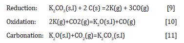
As one would think that the potassium was distributed differently in the two impregnation methods, this may indicate that it is the oxidation (reaction [10]) or the carbonization reaction (reaction [11]) that is rate determining reactions. The rate of reaction [9] may be different for the two impregnation methods, however if the reaction is much faster than the subsequent reactions, the overall rate will not be determined by the impregnation method. The mechanical strength of charcoal is one of the weaknesses of the use of charcoal. The handling and transport to the furnace will produce fines, which is unwanted in the charge mix. The mechanical strength of charcoal particles was measured after heating to 1100°C in Ar (Figure 8) and with further densification (Figure 9). The mechanical strength will vary perpendicular and parallel to the pores in the charcoal, the trend is however the same. The variation from particle to particle is large, and hence more particles must be done to get a good average. There is however an indication that the particles will increase in strength during the heating, however that the densification is not affecting the strength that much. Kaffash (2021) [24] however argued for an increased strength with increased densification. This was however not seen here. It can be argued that the difference between the different particles are so large that the variance is larger than the effect. Also when it comes to the abrasion strength, as shown in Figure 10, the reduction of fine formation is largest with the heating step, but that the densification also will have some influence.


Conclusion
By densifying the charcoal by cracking methane to C and H2 gas, the CO2 reactivity in charcoal can be decreased and the mechanical strength may be increased. It is shown that the charcoal used can take up 30% extra carbon during the densification process, and the limit is probably not met in these experiments. Around 50% of the methane is cracked, which means that the off gas from the densification process will be a mixture of unreacted methane and H2 gas. It is expected that a higher yield can be obtained with optimization of the process. The CO2 reactivity is studied for potassium impregnated charcoal, densified charcoal and metallurgical coke as a reference. While charcoal typically has 10 times higher reactivity than coke, the CO2 reactivity for potassium impregnated coke is about 80% of the charcoal, and the impregnated densified charcoal will be in between. With more than 4-5%K present the reactivity of coke and charcoal will hence be more similar. In many processes like e.g. the Mn-ferroalloy process the potassium content is expected to be in this area. K gasimpregnation and solution impregnation gives the same reactivity, and hence it is believed that it is the oxidation (reaction [8]) or the carbonization reaction (reaction [9]) that is rate determining reactions. Both the compression strength and the mechanical strength increase more in the heating part of the densification, than in the densification process itself.
Acknowledgement
The work is funded by the Norwegian Research Council and the Norwegian ferroalloy producers research association under the projects Controlled Tapping 267621, SFI Metal production 237738, Biomet 336175 and BioCarbUp 294679/E20.
References
- Westfall LA, Davourie J, Ali M, McGough D (2016) Cradle-to-Gate Life Cycle Assessment of Global Manganese Alloy Production. The International Journal of Life Cycle Assessment 21 (11): 1573-1579.
- Monsen B, Grønli M, Nygaard L, Tveit H, et al. (2001) The Use of Biocarbon in Norwegian Ferroalloy Production. INFACON 9(1): 268–276.
- Mathieson J, Rogers H, Somerville M, Jahanshahi S, Ridgeway P (2011) Potential for the Use of Biomass in the Iron and Steel Industry. Proceedings of the Chemeca, Sydney, Australia.
- Olsen S, Tangstad, M, Lindstad T (2007) Production of Manganese Ferroalloys; Tapir: Trondheim.
- Tangstad M (2013) Manganese Ferroalloys Technology. In Handbook of Ferroalloys; Elsevier pp. 221-266.
- Tangstad M, Beukes JP, Steenkamp JD, Ringdalen E (2018) Chapter 14: Coal-Based Reducing Agents in Ferroalloys and Silicon Production. In Isabel Suarez-Ruiz, Maria Antonia Diez, Fernando Rubiera (Ed), New Trends in Coal Conversion Combustion, Gasification, Emissions, and Coking, Woodhead Publishing; Woodhead Publishing.
- Hosum BD (2020) Reduction Rate of SiMn Slags with Different Carbon Materials. Master thesis, NTNU.
- Ergun S (1956) Kinetics of the Reaction of Carbon with Carbon Dioxide. J Phys Chem 60(4): 480-485.
- Mianowski, A, Radko, T, Siudyga, T (2016) Influence of Initial Assumptions on the Kinetic Models of CO2 Gasification of Chars and Cokes in Solid Phase. Journal of Thermal Analysis and Calorimetry 126(3): 1911-1923.
- Huo W, Zhou Z, Chen X, Dai Z, Yu G (2014) Study on CO2 Gasification Reactivity and Physical Characteristics of Biomass, Petroleum Coke and Coal Chars. Bioresource Technology 159(1): 143–149.
- Kwon TW, Kim SD, Fung DPC (1988) Reaction Kinetics of Char-CO2 Gasification. Fuel 67 (4): 530–535.
- Hovd B (2017) CO2 Reactivity of Coke and Charcoal. Unpublished work.
- Kaffash H, Tangstad M (2022) CO2 Gasification of Densified Biomass: The Influence of K on Reaction Rate. JOM.
- Ishak R (2007) Degree of Prereduction Witout Coke Consuption in Industrial Furnaces. INFACON 11(1): 268-280.
- Alam M, Debroy T (1984) The Effects of CO and CO2 on the Rate of Na2CO3 Catalyzed Boudouard Reaction. Metallurgical Transactions B 15(2): 400-403.
- Tangstad M (1996) The High Carbon Ferromanganese Process - Coke Bed Relations. PhD, NTH, Trondheim, Norway.
- Rao YK, Adjorlolo A, Haberman JH (1982) On the Mechanism of Catalysis of the Boudouard Reaction by Alkali-Metal Compounds. Carbon 20(3): 207-212.
- Kirtania K, Axelsson J, Matsakas L, Christakopoulos P, Umeki K, Furusjö E (2017) Kinetic Study of Catalytic Gasification of Wood Char Impregnated with Different Alkali Salts. Energy 118(1): 1055-1065.
- Liu Y, Wang Z, Wan K, Lv Y, Xia J, et al. (2018) In Situ Measurements of the Release Characteristics and Catalytic Effects of Different Chemical Forms of Sodium during Combustion of Zhundong Coal. Energy Fuels 32(6): 6595-6602.
- Saito Y, Tsukamoto C (2022) Hot Coke Strength in CO2 Reaction. ISIJ International 62 (3): 606-608.
- Kurauchi MHN, Takano C, Narita CY, Mourao MB (2014) LAB SCALE TEST OF CHARCOAL COMPRESSION STRENGTH: A NEW APPROACH. 44o Seminário de Redução de Minério de Ferro e Matérias-primas, 15o Simpósio Brasileiro de Minério de Ferro e 2o Simpósio Brasileiro de Aglomeração de Minério de Ferro, Belo Horizonte - Brasil 44(44): 4909-4916.
- kumar M, Gupta RC (1997) Influence of Carbonization Conditions on the Pyrolytic Carbon Deposition in Acacia and Eucalyptus Wood Chars. Energy Sources 19(3): 295-300.
- M Kumar, BBV, RC Gupta (1999) Mechanical Properties of Acacia and Eucalyptus Wood Chars. Energy Sources 21(8): 675-685.
- Kaffash H, Surup GR, Tangstad M (2021) Densification of Biocarbon and Its Effect on CO2 Reactivity. Processes 9(193): 1-13.
- Kvam KR, Larsen B, Øye (H 2000) Potassium Resistance Testing of Carbon Electrode Materials. In Deutsche Keramische Gesellschaft pp. 433-434.
- Lindstad T, Syvertsen M, Ishak R, Arntzen HB (2004) The Influence of Alkalis on the Boudouard Reaction. International Ferroalloy Conference proceedings X, Cape Town, South Africa.
- Solhaug E (2021) Densified Biocarbon and the Effect of Potassium on the CO2
-

This work is licensed under a Creative Commons Attribution-NonCommercial 4.0 International License.


