 Research Article
Effects of Element Directivity in Linear-Array Photoacoustic Imaging
Moein Mozaffarzadeh1,2, Bahador Makkiabadi1,3* and Mohammad Mehrmohammadi4
1Research Center for Biomedical Technologies and Robotics, Institute for Advanced Medical Technologies, Iran
2Department of Biomedical Engineering, Tarbiat Modares University, Iran
3Department of Medical Physics and Biomedical Engineering, School of Medicine, Tehran University of Medical Sciences, Iran
4Department of Biomedical Engineering, Wayne State University, USA
Bahador Makkiabadi, Research Center for Biomedical Technologies and Robotics, Institute for Advanced Medical Technologies and Department of Medical Physics and Biomedical Engineering, School of Medicine, Tehran University of Medical Sciences, Iran.
Received Date: October 05, 2018; Published Date: October 23, 2018
Abstract
Photoacoustic imaging (PAI) is an emerging medical imaging modality with a steady growth in both pre-clinical and clinical applications. In linear-array PAI, beamformers play a significant role in the image reconstruction procedure. Generally, beamformers assume a point- like model for the elements of the array, and the elements are assumed to be omnidirectional. In this study, we investigated the effects of receiver element directivity on the Photoacoustic (PA) image formation procedure where delay-andsum (DAS) and delay-multiply-and-sum (DMAS) algorithms have been used as beamformers. The proposed method is evaluated experimentally (wire phantom and ex vivo imaging). It has been shown that the contribution of the directivity of the transducer elements improves the PA image quality. The results show that using the directivity, the sidelobes of the formed image (wire phantom) by DAS are attenuated about 20 %, compared to when directivity is not used. Moreover, signal-to-noise ratio achieved by DAS and DMAS is improved by about 12.5 % and 11.3 %, respectively.
Abbreviations: PAI: Photo Acoustic Imaging; PA: Photo Acoustic; DAS: Delay-And-Sum; DMAS: Delay-Multiply-And-Sum; MV: Minimum variance; DS-DMAS: Double stage- Delay-Multiply-And-Sum; MCF: Modified Version of the Coherence Factor; US: Ultrasound
Introduction
Photoacoustic imaging (PAI) has been used in different case of studies such as cancer detection and staging [1,2] monitoring the oxygenation in blood vessels [3] and functional imaging [4]. In PAI, a laser pulse irradiates the sample/tissue, resulting in local temperature rise, and due to thermoelastic expansion, pressure waves (in the form of ultrasound (US) waves) are generated [5,6]. Some of the PAI systems are based on a single-element/ring array US transducer while it brings difficulties for translation into clinical applications [7,8]. Therefore, recently dual-modal clinical US and photoacoustic (PA) imaging have been reported for better clinical translation [9,10]. Clinical US/PA systems work with linear, convex or phased array transducers. The focus of this paper is the lineararray case.
Linear-array transducers provide an angle view of about 40 degree, which is not satisfying (in comparison with the ring-array transducer, which get a full 360 degree view) [11]. Thus, generally, the quality of reconstructed images in linear-array scenario is low (compared to circular tomography) [12,13]. In linear-array PAI, beamforming algorithms can be used for image reconstruction. In linear-array scenario, enhanced image formation algorithms can be helpful with image improvement [14,15]. Delay-and-sum (DAS) is the most commonly used beamformer as a result of its simple implementation. However, it leads to a low quality image due to its blindness. Minimum variance (MV) can be used to address the low resolution of DAS, but it leads to high sidelobes [16]. Matrone et al. [17] proposed a new beamformer for US imaging named delaymultiply- and-sum (DMAS), providing a higher contrast compared to DAS. DMAS was initially used in PAI [18]. Double stage (DSDMAS), in which two stages of DMAS are applied to gain a higher contrast and resolution in comparison with DMAS, was introduced for linear-array PAI [19-21]. In addition, a Modified Version of the Coherence Factor (MCF) was introduced based on the DMAS, and it was shown that it provides a higher contrast compared to conventional CF [22,23]. In order to improve the resolution of DMAS, MV and its eigenspace version have been combined with the expansion of DMAS [24,25].
Directivity was investigated in the case that MV was used as the beamformer for linear-array Ultrasound (US) imaging. Also, it has been used for image improvement in circular PA tomography [14]. It has been shown that considering the element directivity decreases the error of the desired signal estimation and increases the spatial resolution of the formed image [26]. In this study, the effects of the element’s directivity are evaluated where DAS and DMAS beamformers are used as the reconstruction algorithms. The results show that the contribution of the elements directivity would improve the PA image quality.
Materials and Methods
Effects of directivity
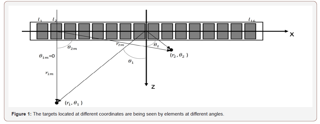
Generally, beamformers assume a point-like model for the elements of array. To put it more simply, the directivity of the element of array is not considered in image reconstruction procedure, and the elements are assumed to be omnidirectional. In [26], it has been shown that discarding directivity of the transducers affects the formed images. The detected signals from a target can be strengthened or weakened based on the position of the target. In other words, the directivity pattern of the transducer influences the detected signals, and also the formed images. To illustrate this, consider (Figure 1) where there are two targets located at (r1, rθ1) and (r2, rθ2). Assuming r1m = r2m, the PA signals generated by these targets will arrive to the element l2 simultaneously. The detected signal caused by the target located at (r1, rθ1) would be dominant since the angle rθ1m coincides with the direction of the maximum radiation of the element l2. On the other hand, the obtained signal caused by the target located at (r2, rθ2) would be weakened since the angle rθ2m makes the target far from the direction of the maximum radiation of the element l2. Consequently, an erroneous signal which presents information about the target located at (r2, rθ2) is detected by the element l2. To address this problem, the observation angle needs to be considered in the PA image reconstruction algorithms. When PA signals are detected by a linear-array of US transducers, beamforming algorithms such as DAS can be used to reconstruct the PA image. DAS can be written as follows:

where yDAS(k) is the output of the beamformer, k is the time index, M is the number of elements of array, and xi(k) and Δi are the detected signals and the corresponding time delay for detector i, respectively. Implementing the DAS beamformer is simple which is why it is the most common beamforming algorithm in US and PAI. However, this algorithm provides a low off-axis signal rejection and noise suppression. Consequently, DAS results in reconstructed images having high levels of sidelobe and a low resolution. To address the limitations of DAS, DMAS was suggested in [17]. Similar to DAS, DMAS calculates corresponding samples for each element of the array based on the delays, but samples go through a correlation process before adding them up. The DMAS formula is as follows:

To overcome the dimensionally squared problem of (2), following modifications are suggested in [17]:

Including the directivity in the beamforming algorithm results in the following equation:

where rθik is the angle between the element i and pixel k. The directivity factor can be expressed as

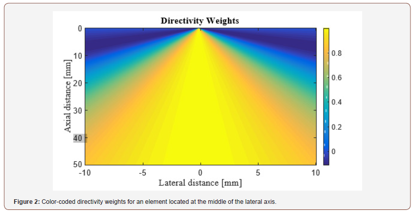
where d is the width of the elements. The image of the directivity weights for the element located at the middle of the lateral axis is shown in (Figure 2). As can be seen, as far as lateral distance increases, the generated signals are weakened.
Wire-target imaging
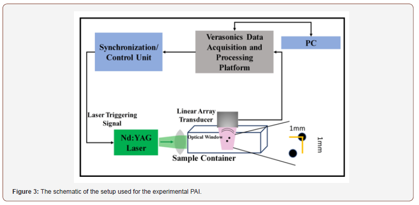
For validation of the proposed method, an experiment was performed in which the phantom consists of 2 light absorbing wires with diameter of ,150μm. The wires were placed 1mm> apart from each other. In this experiment, we utilized a Nd: YAG pulsed laser, with the pulse repetition rate of 30Hz at wavelengths of 532nm. A programmable digital ultrasound scanner (Verasonics Vantage 128), equipped with a linear-array transducer (L11-4v) operating at frequency range between 4 to 9MHz was utilized to acquire the PA RF data. A high speed FPGA was used to synchronize the light excitation and the PA signal acquisition. The schematic of the developed imaging system is shown in (Figure 3).
Ex Vivo Imaging
In this study, an ex vivo experimental tissue study has been designed to evaluate the performance of the proposed algorithm. A piece of a breast tissue (about 4cm 4cm 3cm) is extracted from a new sacrificed chicken. Two pencil leads with a diameter of 0.5mm are embedded inside the breast tissue, having an axial distance of about 5mm. Figure 4 shows the photographs of the imaged tissue. The PA signals are collected with a combined linear US/PA imaging probe [27].
Result and Discussion
The experimental reconstructed PA images using DAS and DMAS beamformers are shown in (Figure 5) and (Figure 6) (ex vivo) where the directivity has been used for the images shown in the second row. It should be noticed that the transducer surface is perpendicular to the targets, so it is expected to see the cross sections of them. Comparison of (Figure 5a & 5C) shows that the contribution of the directivity in the reconstruction procedure improves the PA image, especially with the reduction of artifacts around the point targets. Indeed, the sidelobes are reduced, and the cross section of the wire targets are better detectable. Also, the effects of the directivity on DMAS beamformer can be seen in (Figure 5d) where the artifacts are better reduced compared to (Figure 5b). To evaluate the reconstructed images in more details, the lateral variations of the (Figure 5) at the depth of 22mm are shown in (Figure 7). As is demonstrated using the red circles and arrows, the contribution of the directivity degrades the level of sidelobes for about 7dB, which results in a higher image quality. For quantitative evaluation of the wire phantom study, the signalto- noise ratio (SNR) is presented in Table 1. The SNRs are calculated using the following formula [20,24]:

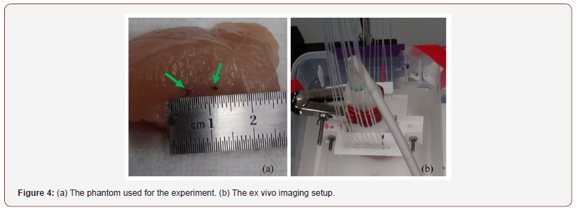
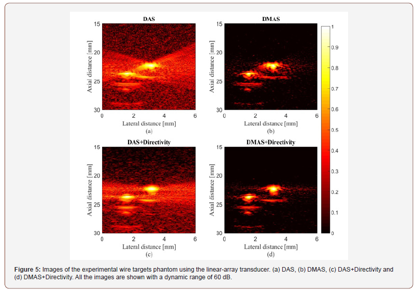
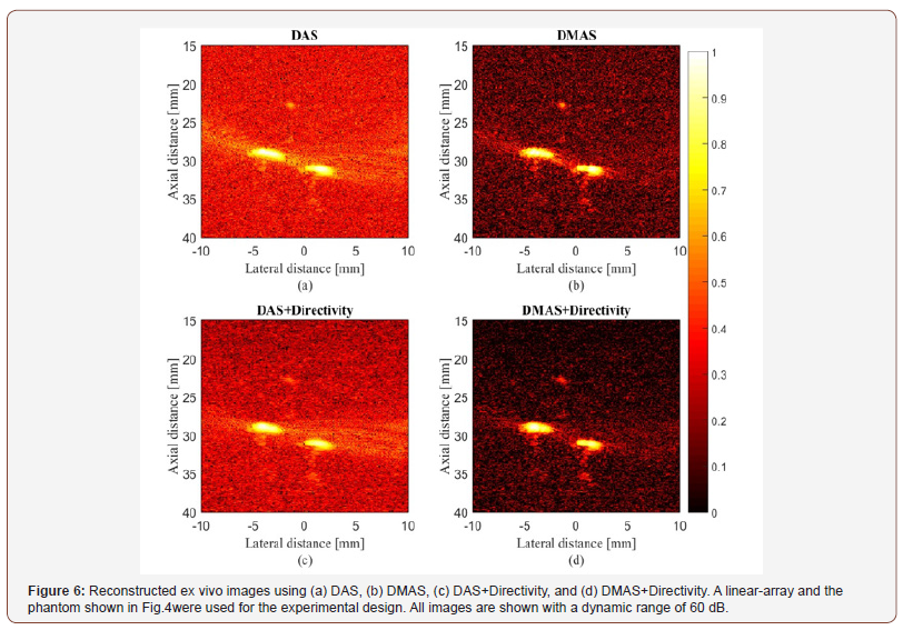
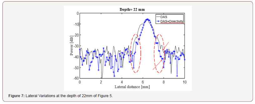
Table 1: SNR (dB) values at the different depths of the Figure 5.

where Psignal and Pnoise are difference of maximum and minimum intensity of a rectangular region including a point target, and standard deviation of the noisy part of the region, respectively [20,24]. As shown, the contribution of the directivity for both the beamformers leads to a higher SNR. In other words, the presence of noise would be reduced when the directivity is used. For instance, at the depth of 22mm using the directivity leads to about 8dB and 12dB SNR improvement, for DAS and DMAS, compared to the case the directivity is not used. As seen in Figure 6, the proposed method results in background noise suppression (the noise is generated because of the chicken tissue). We have used Contrast Ratio (CR) for quantitative evaluation of the ex vivo images [20]. As demonstrated in Table 2, using the proposed method results in 2dB increment in CR metric. This is mainly due to the fact that directivity suppresses off-axis signals and artifacts. It should be noticed that the directivity plays a significant role in the improvement of the beamformed PA images. In the cases that the targets of imaging are much more complicated or the level of sidelobes are of importance in the image, using the proposed method would make the target detection much easier, as it did for the images obtained for the ex vivo imaging, which is close to practical condition. Moreover, as is demonstrated, not only does the directivity improve the reconstructed images by DAS, but also it enhances the formed images by DMAS. In other words, even though DMAS reduces the sidelobes compared to DAS, using directivity would help with better sidelobes reduction and higher image quality. The presented results can be generalized to the cases other beamformers are utilized. The presented method in this paper has a low complexity, with an order of complexity of M (O(M)) and can be easily used in clinical PAI devices. As further works, the performance of the proposed method should be evaluated for in vivo imaging and implemented on a FPGA for practical use.
Table 2: CR (dB) values at the different depths of the Figure 6.

Conclusion
In this paper, the effects of contribution of the element’s directivity have been investigated for linear-array PAI. The proposed method has been evaluated experimentally (wire phantom and ex vivo imaging). The results of wire phantom indicated that it improves both the images reconstructed by the DAS and DMAS (7dB lower sidelobes for DAS). For quantitative evaluation, SNR and CR have been used. It was shown that the proposed method results in 12 dB SNR improvement, at the depth of 22mm, for the DMAS beamformer. In addition, CR is increased about 2dB using the elements directivity (for both the used beamformers).
Acknowledgment
None.
Conflict of Interest
None.
References
- M Mehrmohammadi, S Joon Yoon, D Yeager, SY Emelianov (2013) Photoacoustic imaging for cancer detection and staging. Curr Mol Imaging 2(1): 89-105.
- Y Lou, W Zhou, TP Matthews, CM Appleton, MA Anastasio (2017) Generation of anatomically realistic numerical phantoms for photoacoustic and ultrasonic breast imaging. J Biomed Opt 22(4): 1015- 041015.
- RO Esenaliev, IV Larina, KV Larin, DJ Deyo, M Motamedi, et al. (2002) Optoacoustic technique for noninvasive monitoring of blood oxygenation: a feasibility study. Appl Opt 41(22): 4722-4731.
- J Yao, J Xia, KI Maslov, M Nasiriavanaki, V Tsytsarev, et al. (2013) Noninvasive photoacoustic computed tomography of mouse brain metabolism in vivo. Neuroimage 64: 257-266.
- LV Wang, J Yao (2016) A practical guide to photoacoustic tomography in the life sciences. Nature Methods 13, 627-638.
- Lei Li, Liren Zhu, Cheng Ma, Li Lin, Junjie Yao, et al. (2017) Single-impulse panoramic photoacoustic computed tomography of small-animal wholebody dynamics at high spatiotemporal resolution. Nature Biomedical Engineering1 Art–No: 0071.
- P Omidi, M Zafar, M Mozaffarzadeh, A Hariri, X Haung, et al. (2018) A novel dictionary- based image reconstruction for photoacoustic computed tomography. Appl Sci 8: 1570.
- M Mozaffarzadeh, V Periyasamy, M Pramanik, B Makkiabadi (2018) Efficient nonlinear beamformer based on pth root of detected signals for linear-array photoacoustic tomography: application to sentinel lymph node imaging. J of Biomedical Optics, 23(12).
- K Sivasubramanian, V Periyasamy, RA Dienzo, M Pramanik (2018) Hand-held, clinical dual mode ultrasound- photoacoustic imaging of rat urinary bladder and its applications. J biophotonics 11(5).
- J Kim, S Park, Y Jung, S Chang, J Park, et al. (2016) Programmable realtime clinical photoacoustic and ultrasound imaging system. Sci. reports 6 Art-no: 35137.
- K Daoudi, P Van DB, O Rabot, A Kohl, S Tisserand, et al. (2014) Handheld probe integrating laser diode and ultrasound transducer array for ultrasound/photoacoustic dual modality imaging. Opt express 22(21): 26365-26374.
- Y Zeng, D Xing, Y Wang, B Yin, Q Chen (2004) Photoacoustic and ultrasonic coimage with a linear transducer array. Opt Lett. 29(15): 1760-1762.
- R Paridar, M Mozaffarzadeh, M Mehrmohammadi, M Orooji (2018) Photoacoustic image formation based on sparse regularization of minimum variance beamformer. Biomedical Optics Express 9(6): 2544- 2561.
- D Yang, D Xing, S Yang, L Xiang (2007) Fast full-view photoacoustic imaging by combined scanning with a linear transducer array. Optics Express 15(23): 15566-15575.
- Y Wang, D Wang, Y Zhang, J Geng, JF Lovell, et al. (2016) Slit-enabled linear-array photoacoustic tomography with near isotropic spatial resolution in three dimensions. Opt Lett 41(1): 127-130.
- JF Synnevag, A Austeng, S Holm (2009) Benefits of minimum-variance beamforming in medical ultrasound imaging. IEEE Transactions on Ultrasonics, Ferroelectrics, Freq Control 56(9): 1868-1879.
- G Matrone, AS Savoia, G Caliano, G Magenes (2015) The delay multiply and sum beamforming algorithm in ultrasound b-mode medical imaging. IEEE Transactions on Medical 34(4): 940-949.
- J Park, S Jeon, J Meng, L Song, JS Lee, et al. (2016) Delay-multiply-andsum- based synthetic aperture focusing in photoacoustic microscopy. J biomedical optics 21(3): 036010.
- M Mozaffarzadeh, M Sadeghi, A Mahloojifar, M Orooji (2018) Doublestage delay multiply and sum beamforming algorithm applied to ultrasound medical imaging. Ultrasound in Medicine & Biology 44(3): 677-686.
- M Mozaffarzadeh, A Mahloojifar, M Orooji, S Adabi, M Nasiriavanaki (2018) Double-stage delay multiply and sum beamforming algorithm: Application to linear-array photoacoustic imaging. IEEE Transactions on Biomed Eng 65(1): 31-42.
- M Mozaffarzadeh, A Hariri, C Moore, JV Jokerst (2018) The double-stage delay-multiply-and-sum image reconstruction method improves imaging quality in a led-based photoacoustic array scanner. Photoacoustics 12: 22-29.
- M Mozaffarzadeh, Y Yan, M Mehrmohammadi, B Makkiabadi (2018) Enhanced linear-array photoacoustic beamforming using modified coherence factor. J Biomed Opt 23(2): 026005.
- R Paridar, M Mozaffarzadeh, V Periyasamy, M Basij, M Mehrmodammadi, et al. (2018) Validation of delay-multiply-and-standard-deviation weighting factor for improved photoacoustic imaging of sentinel lymph node. J Biophotonics: e201800292.
- M Mozaffarzadeh, A Mahloojifar, M Orooji, K Kratkiewicz, S Adabi, et al. (2018) Linear-array photoacoustic imaging using minimum variancebased delay multiply and sum adaptive beamforming algorithm. J Biomed Opt 23(2): 1-15.
- M Mozaffarzadeh, A Mahloojifar, V Periyasamy, M Pramanik, M Orooji (2018) Eigenspace-based minimum variance combined with delay multiply and sum beamformer: Application to linear-array photoacoustic imaging. IEEE Journal of Selected Topics in Quantum Electronics 1-8.
- H Hasegawa, H Kanai (2015) Effect of element directivity on adaptive beamforming applied to high-frame-rate ultrasound. IEEE Trans Ultrason Ferroelectr Freq Control 62(3): 511-523.
- Y Yan, M Basij, E Hemandez-Andrade, S Hassan, M Mehrmohammadi (2017) Endocavity ultrasound and photoacoustic imaging system to evaluate fetal brain perfusion and oxygenation: Preliminary ex vivo studies. IEEE International Ultrasonics Symposium (IUS): 1-1.
-
Moein M, Bahador M, Mohammad M. Effects of Element Directivity in Linear-Array Photoacoustic Imaging. Arch Biomed Eng & Biotechnol. 1(1): 2018. ABEB.MS.ID.000504.
-
Photoacoustic imaging, US transducer, Wire phantom, Ex vivo imaging, Ring-array transducer, circular tomography, Phased array transducers, Beamformers, sidelobes, Omnidirectional, Blood vessels, Pressure waves, Dual-modal clinical US, conventional CF, Low off-axis signal rejection, Noise suppression
-

This work is licensed under a Creative Commons Attribution-NonCommercial 4.0 International License.


